
From Stereo Pair to Lenticular Print
Michael Brown ISU STEREOSCOPY N108, ISSUE 4, 2016
Stereo photography enthusiasts often want to share their pictures with others not familiar with the art form. The general public is sometimes put off by having to use a stereoscope, special glasses, or free view eye techniques to view 3D stereo pictures. 3D lenticular prints are easy to view and can be passed around or be displayed as art on the wall of a home or gallery.
Lenticular prints typically have reduced depth compared to a scene viewed with a stereoscope. One should not expect to make lenticulars that can match the view through a stereoscope or the display of a 3D TV; that isn’t possible with this medium. However a well made lenticular is really something special and people are generally impressed with the two to four inches of depth that small lenticular prints can display.
Most 3D enthusiasts are aware that lenticular prints are made with a series of frames, not just the two views from a stereo pair. However, there are conversion techniques that can produce lenticular prints from stereo pairs, and perhaps the easiest involves using software to create a depth map and frame series. Success with this technique is definitely scene dependent. Sometimes the software works great just in auto mode and other times it doesn’t work at all. My suggestion is to start with a simple stereo view composition and experiment.
Both free and commercial software exists for this application. For the purpose of this article I will describe the use of Triaxes StereoTracer Pro, which is commercial software that runs on Windows based PC computers. This software can take an MPO file, or a stereo pair from scanned film, and create dual gray scale depth maps for both left and right images. It then uses those depth maps and the stereo pair to generate a multi-frame sequence of views representing different horizontal parallaxes. The multi-frame sequence can then be used with an interlacing software program to produce a lenticular print.
I should mention that this conversion process will produce a lenticular print with good visual depth but should not be expected to rival scenes that are actually photographed as a frame series with differing horizontal parallax. In my opinion, the best results are still achieved by photographing a scene with either a slide bar, or multi-camera rig where the total stereo base used is three to six times wider than normal.
To illustrate this article, I selected an MPO file made with the Fuji W1 camera.

Parallel view of an MPO file from Fuji W1 camera.
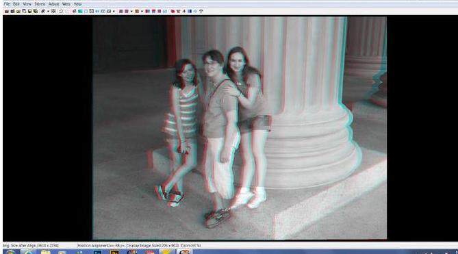
Anaglyph of the MPO.
Users often process their MPOs with StereoPhoto Maker (SPM) software to set the stereo window. Setting the window for lenticular differs from traditional stereoscopy. Due to the limited depth budget of a lenticular print, it is usually best to place the part of the scene you want to be the sharpest at the window plane. This is sometimes referred to as the plane of zero parallax, or zero point. The other scene elements should have both negative and positive parallax, so the foreground elements come forward through the stereo window and the background recedes behind the window. The window in this case also represents the surface of the lenticular sheet. You can set the window in SPM but I find it faster to use the built-in controls within StereoTracer Pro.
The basic steps to this process are:
- Launch Triaxes StereoTracer Pro and open the MPO.
- Use the buttons for Auto Alignment and Parallax correction.
- Select the best looking of the nine pre-generated depth maps.
- Generate the frame sequence. As a starting point try: 36 frames 7% parallax, and a plane of zero parallax of 127.
- Export and save the frames.
- Interlace the frame series and print.
- Bond the lenticular sheet to the print.[/box]
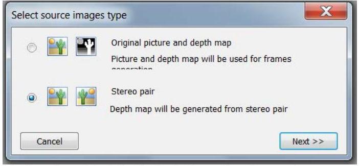
Select Source Images Type: This dialog box lets the user choose between using an existing image and depth map, or creating a new depth map from a stereo pair.
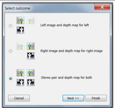
Select Outcome: This dialog box lets the user create a depth map for either the left, right, or both images from the pair. Using the “both” option helps simulate the look around effect in the software generated frame sequence.
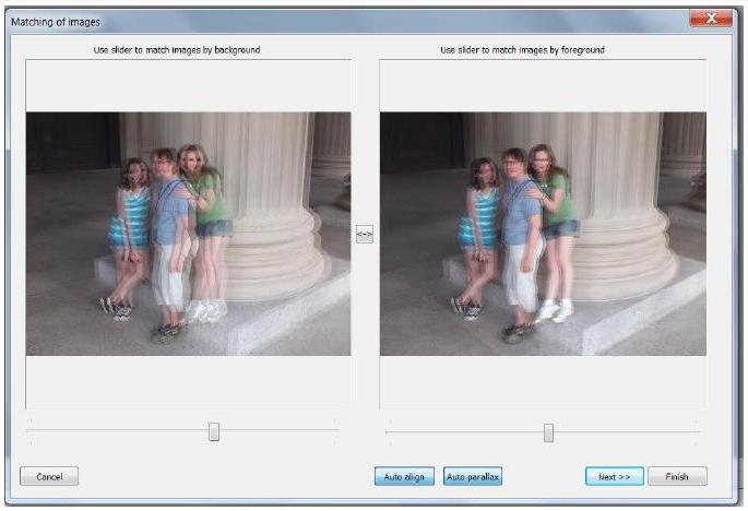
Matching of Images Dialog Box: You can manually align the image foreground and background, or select the options of Auto Align and Auto Parallax.
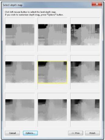
Select Depth Map: StereoTracer Pro automatically creates nine different depth map variations. The user can select which one looks best.
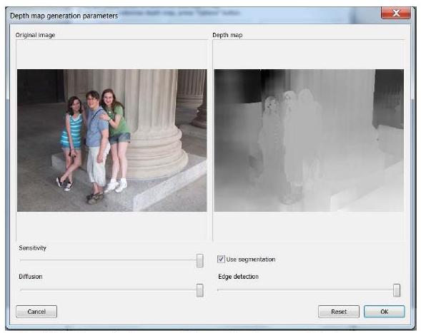
Depth Map Generation Parameters: If none of the nine generated depth maps are suitable, the user can alter sensitivity, diffusion, and edge detection variables to achieve a different result.
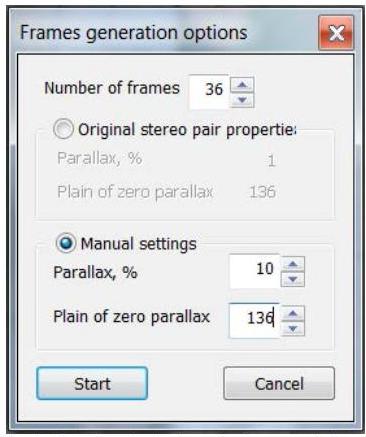
Frames Generation Options: Once the depth map has been created, the software allows the user to select the number of frames desired, the percentage of parallax, and the plane of zero parallax. In this example, I chose to generate 36 frames instead of the default of 12, and also changed the values for the Parallax percentage and the plane of zero parallax from the default of 7% and 127 to 10% and 136.
(These last two steps are not covered in this article.)
I use StereoTracer Pro to generate frame sequences from 3D MPO files or scanned stereo view slides. StereoTracer Pro can export the frame set to their 3DMasterKit software for interlacing. However, I do not own that software, and use a different software program to do the interlacing.
I generally can see obvious errors in the auto generated depth maps and frame sequences created by StereoTracer Pro. Such errors are usually not critical enough to concern me, and the prints I make turn out reasonably well. I print my interlaced files using an Epson 4900 printer on glossy letter sized paper and use Micro Lens Technology brand 60 LPI 3D lenticular sheets.
If you’re not happy with the printed lenticular, you can change the default values used by the software for frame generation. There are three variables that can be changed: the number of frames generated, the percent of parallax deviation, and the placement of the plane of zero parallax.
I generally like to use between 10 and 100 frames to make my 3D lenticulars. The more frames used, the less jitter in the final print when it is rotated in the hand. The jitter typically occurs in the parts of the image showing the greatest depth. There is a point of diminishing returns—the more frames used, the longer the computer takes to process and the more files that need to be archived. Typically for a 3D conversion I will start with 36 frames. This is different than the software’s default value of 12 frames.
The parallax setting controls the depth budget of the scene. Higher values result in more depth and lower values result in reduced depth. For parallax displacement, I have tested a variety of lenticular sheets and find that keeping values below 5% for the main subject gives me good in-focus results. As parallax exceeds that percentage, the print has greater depth, but begins to lose sharpness. Triaxes has a default setting of 7, which is a reasonable starting point. The available range is 0-100. Zero would have no depth and 100 would give you the greatest depth. But understand that higher values will also produce more edge artifacts during frame generation. The Triaxes software manual suggests keeping the parallax setting under 10.
The final variable is placement of the plane of zero parallax which allows you move the scene forward or backward. The default setting is 127, with a range of 0-255. At 127 half the depth should appear in front of the lens surface, and half should appear behind
the lens surface. A value of zero would move the entire scene depth forward in front of the lenticular sheet, and a value of 255, would place all the depth behind the surface of the lenticular sheet.
StereoTracer Pro has another option for 3D frame generation. Rather than have the software create the depth map from the stereo pair, the user can supply a hand drawn depth map. I don’t feel I have the skill to draw my own depth maps, but I found a service on-line (www.depthmask.com) that will produce depth maps from user supplied digital photographs.
I sent depthmask.com three MPOs and within 24 hours had received the depth maps back by e-mail. After loading a 2D image (the right frame of the MPO), and the hand drawn depth map, I used StereoTracer Pro to produce a frame series with the default settings. The results were quite nice. The lenticulars from the hand drawn depth maps had slightly better depth in the finished lenticular, and fewer edge artifacts than the automatically generated depth maps. I later boosted the parallax setting to 15 (instead of the default 7) for some of my scenes, and was impressed with the results.
Triaxes StereoTracer Pro is an effective software program for generating multi-frame sequences from depth maps. The depth maps can either be automatically created from a user’s supplied stereo pair, or can be hand created using another program or service, such as depthmask.com. Once the multi-frame sequence is created, the frames should be exported and saved. StereoTracer Pro by itself is not a complete solution for making 3D lenticular prints from stereo pairs. Users will also need a software program for interlacing the frame sequences, a topic which will be covered in the future if readers are interested.

The right frame of the MPO.
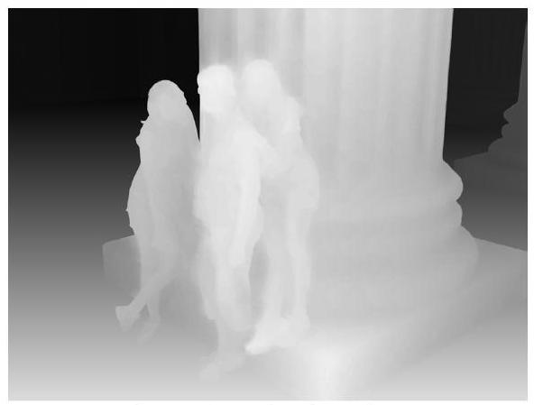
Depth Map from StereoTracer. StereoTracer Pro Depth Map: The right frame depth map automatically created by the software from the MPO file.
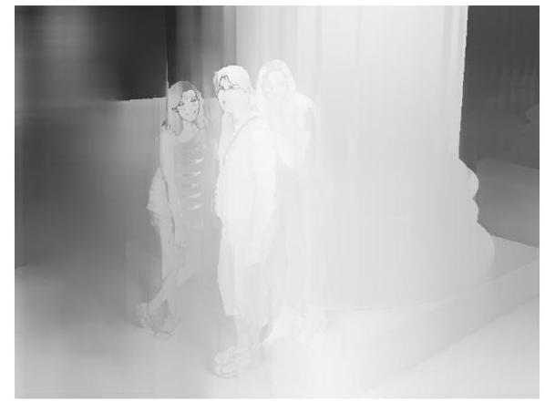
Depth Map from depthmask.com. Hand Edited Depth Map: This depth map was created by the depthmask.com service from the MPO.


