
Create Your Own Lenticular 3D Prints
Introduction
We have all seen them, often in souvenir shops, pictures which seem to jump out of the page due to a lenticular screen effect—or—spectacularly—flip from one image to another or even play a short animated sequence. If you are of a similarly late age as me, born in the 1950s, you might recall the pencil sharpeners that looked like tiny TVs where a Disney character or similar animated on the screen? All these effects are created by the use of a lenticular screen.
Lenticular Screens
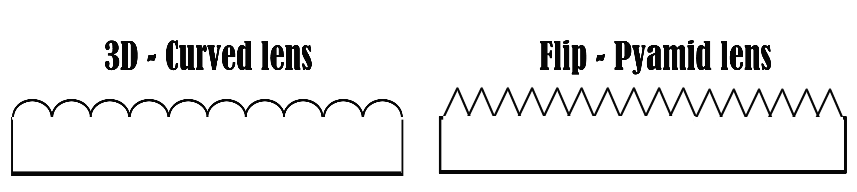
In essence, each screen is an acrylic resin sheet extracted from a moulding/manufacturing process such as to create vertical or horizontal lines of lenses which can vary from 20 to a hundred or more lenses per inch of screen. Most are made in China. Some of the sheets have curved lenses (3D) and others have sharp triangular lenses (flip and animation).
Lenticular Sheets and Home Production of 3D Pictures
The sheets are placed, lens surface up, on a specially prepared image or commercially—the image is printed on the rear smooth side of the sheet. This image is not a normal image which I will explain shortly. The point here though is the image must be in perfect close contact with the sheet and the positioning of the image relative to the horizontal and vertical axis must be micro-perfect. Any mismatch results in failure to produce a good effect.
Failures
A few years ago I purchased a lot of screens from China, adhesive, and a ‘mangle’ type device to create my own lenticular prints. I had an expensive A3 sized printer at the time. The cost of failures trying to get everything to work made me give up! But recently, I decided to try again, and had huge success. I thought I would share with you how to create lenticular 3D at home with the minimum of cost and with maximum success. I cannot say it is an easy process from a start-out point of view but once you obtain success, you can readily produce 3D glasses-free images to sell or simply give to loved ones.
A misunderstanding
Many of the ‘Wow’ 3D lenticular images sold commercially are not in fact true 3D. They consist of flat 2D images positioned such that they seem to cascade forward out of the screen. There is no depth to any artefact in the picture. My guide here is not about that. Such images are not true 3D at all.
Principle And Method
To create a suitable image to place the lenticular sheet on and obtain a 3D effect involves creating a sequence of images around the chosen target and then combining those images into a set of vertical lines such that the number of images are presented in fractured strips one after the other across the screen. Obtaining the images from a stereo pair is difficult and imperfect even using first class software. Setting up say 12 cameras to record 12 images in a range of positions is too expensive and fiddly. The solution is one starts with a single image and you create another image—a grey scale depth map—to ‘inform’ software how to falsely build the other images as seen from the other positions. I have explained this technique in a previous article but I will include a rough guide here too. But before I do, the total method involves having to hand the critical items for printing and presenting an image when it is ready.
Printers and Lenticular Sheets
Fortunately, I have linear sublimation printers, laser printers, and ink jet printers. I had some success with a sublimation printer but the output at 300 DPI was insufficient to my eye to contain enough detail. I reverted to the ink-jet printer. Quite an old one which can produce faithful photographs at 600 DPI. This worked very well. The next thing is the lenticular screens themselves and the issues of quality control and long time shipping from China. And then the major issue I had previously, attaching the final print to the lenticular lens sheet accurately. By chance I discovered a small company in the USA which had good resolutions to these problems. In 3D, it is best initially to produce landscape pictures before trying portrait, which I have not tried yet. The company makes a product called LENTICULAR EVENT FRAMES at 60 LPI (lens per inch) and at 6×4, 7×5, and 8×6 inches in size. These work well. They consist of a lenticular sheet hinged at the bottom on a cardboard back. You slip your finished print into the frame, fiddle around to get it aligned and close it. A transparent silicon band (supplied) is fixed easily to the top to maintain contact between the image (photo-print) and the rear of the frame.
What To Use
Here, then, are the things to obtain to give it a go!
Printer
Epson or HP which offer photographic printing at a minimum of 600 DPI
I am using an HP Photosmart 109A — an old printer now.
Software
Stereo Tracer and 3DMasterKit—required as a must to create the lenticular image faithfully. The only software which has been constant and perfected over many years with lots of hard work from the creator! Get these not other more recent non-entities poorly tested software.
An Image Editor
I use an old version of Photoshop but there are free image editors you can obtain like: GIMP
Ink and Paper
Whatever the printer company says is good advanced photo printing paper. A4 is a good start as you can print 2 x 6×4 inches photos on it.
A Paper Cutter
A guillotine or an accurate paper cutter to cut a 6×4 inch from an A4 sheet. Bad cutting results in failure! Now you are ready to go!
1) Create a grey scale depth-map image;
2) Use StereoTracer to process the colour and grey-scale image;
3) Export the result to 3DMasterKit;
4) Use 3DMasterKit to create the lenticular final image;
5) Print the image;
6) Test and align the image in the EVENT frame.
1. Create a grey-scale depth map image
Use your photo editor to take one of your 2D photos and resize it to 6 inches wide by 4 inches high. However, it also needs to be at a resolution of 600 DPI.. Your original image is unlikely to be at this high resolution. I use a photoshop plug in which up-sizes the photo without just ‘blowing’ it up. It applies Fractal technology to reproduce a relatively un-pixellated image. [Genuine Fractals, now called: ON1 RESIZE at—https:// www.on1.com/products/resize].
There are other software products which do similar but you will need one of them to obtain a higher resolved image from your photo. Once you have the 600 DPI image, duplicate it as a layer. This new layer is the one you are going to ‘mess’ with to get a grey-scale image.
Keep saving you layered image as you work. I save as a photoshop PSD file which retains all the layers. This screen shot shows my creation of a grey scale image. You are seeing the final grey-scale image in the main window.
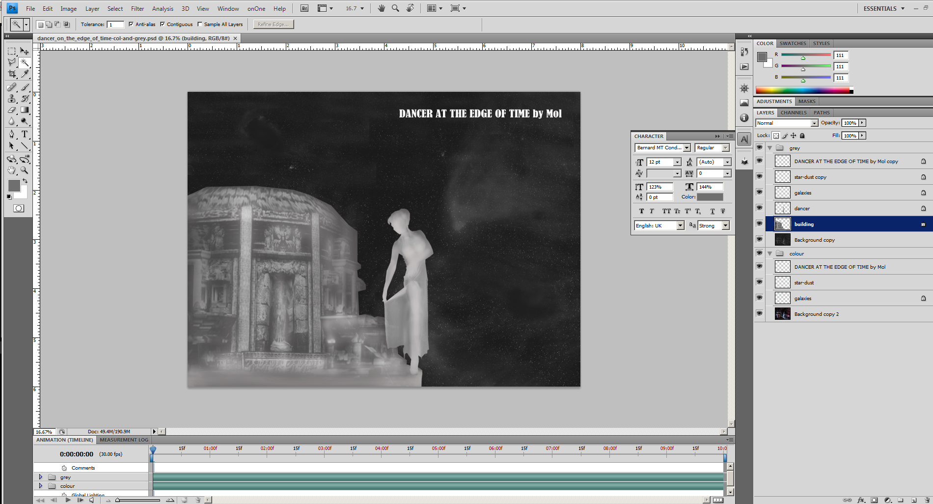
I cut out the girl from a duplicate layer of the picture, saved it as a layer, locked it, then did the same for the building behind her. I then use the paint brush tool to shade in the two objects: the girl and the building. The principle is light colour grey dictates parts of the image or object is foremost and dark colours dictate these objects are further back. If you look at the woman, you will see even here I have made her front leg a brighter shade of grey than the inside of the open dress. It takes practice to do this and I have been doing it for many years. This is a simple image to do, a complex one can take many hours! When you are happy with the results, save the layer stack of grey by flattening all the layers which are grey. Do the same for all the coloured layers so you end up with just one grey layer and one coloured layer. Save as a different file name PSD file. For example ‘colour-and-grey.psd’. You might have to go back and re-edit the multi-layered one to get a good result later on!
Use a Gaussian blur on the grey-scale layer and then save it as grey.jpg. Save the colour level as colour.jpg. Blurring the grey-scale image this way is best. If you do not do it, you might have issues later on, I found! Compare the blurred grey-scale image right to the one above.
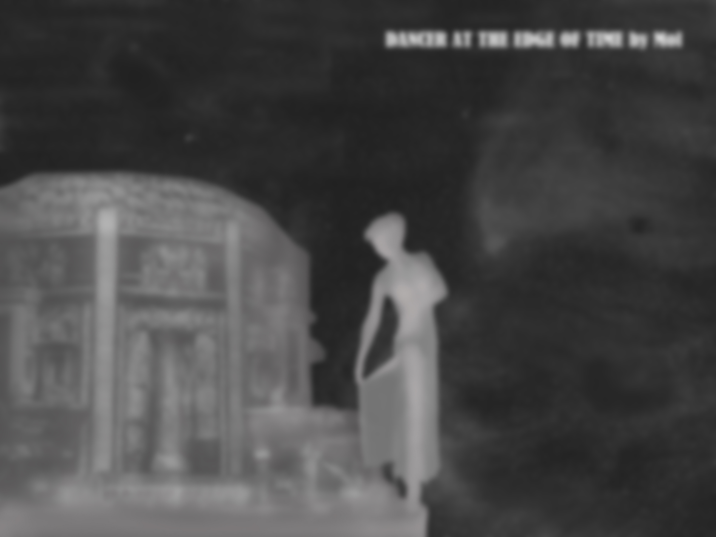
The image is blurred
2. Use StereoTracer to process the colour and grey-scale image
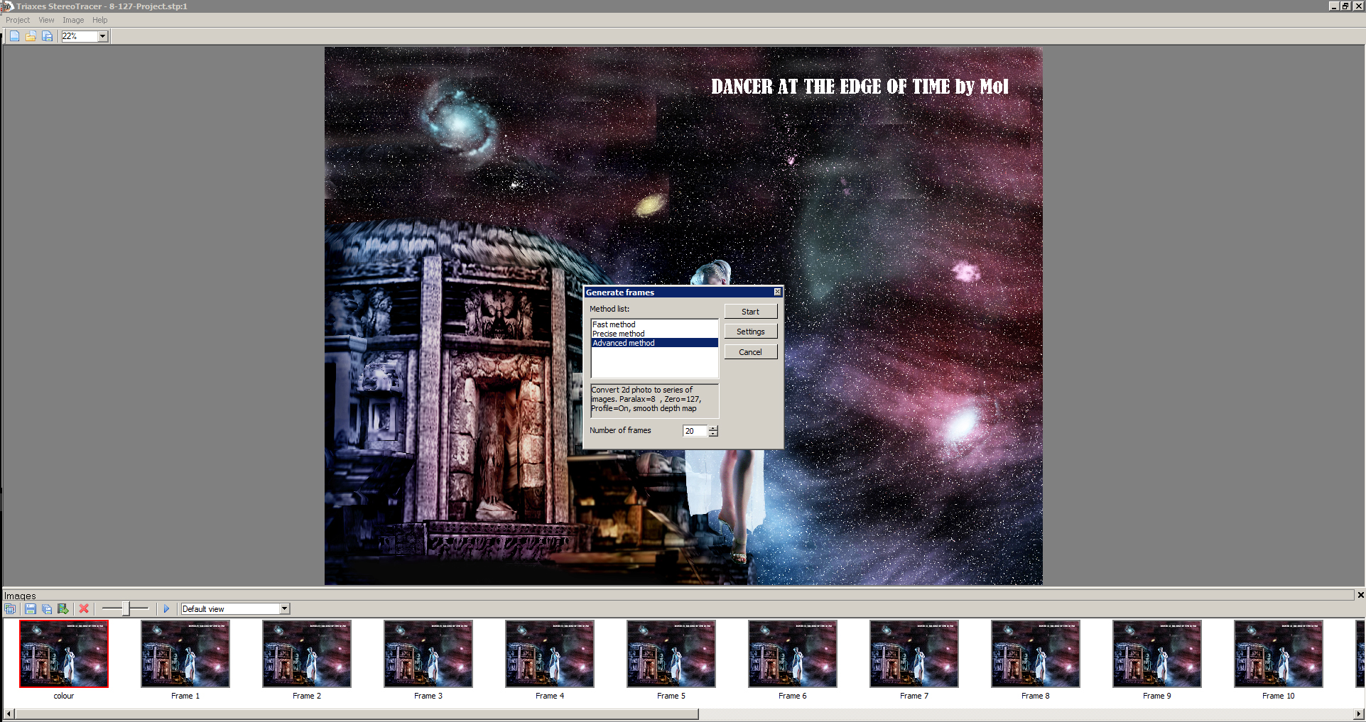
You load the colour image and the grey-scale one into Stereo Tracer. The Screen shot below is slightly misleading as the software has already generated the result I need. But I will regenerate the images by selecting ‘Generate Frames’ from the header menu item IMAGES. Select ‘advanced’ and 20 frames from the menu box then click on settings. Use these values in the next menu box: Parallax=8, Plane of zero parallax=127, Edge filling=Clone, Background reconstruction=95%, Recognition of objects=On, smooth depth map.
You can learn about and play with these variable at another time as you experiment and hone your skill, after reading the help files in the software. Select OK, and then Start. 20 new images will be created. You can animate the result to check it.
The 20 images produced represent 20 slightly different views of the picture objects. These pictures will be utilised to create strips of image fragments which will line up precisely with your lenticular 60 LPI sheet. But first you need to select Images from the top menu and
3. EXPORT TO 3DMasterKit from the drop-down menu.
Note: There is a formula to use to define how many images to produce. The formula is:
N=2*Res/LPI.
Res- printer resolution in Pixels Per Inch.
LPI – lenticular lens per inch.
2 – it’s coefficient which usually gives good results.
Once you have produced your first perfect lenticular print you can use the software help files to learn more and master the technique. I want you to have a first time success to inspire you to create more and become an expert! StereoTracer also has an option to produce a grey-scale depth map image (Saving you all that detailed work in Photoshop or your Image editor) to accept a Left and Right stereo pair and create the depth map for you. Despite a good attempt by the software creator I find my brain is better than the algorithms used in determining an accurate grey-scale depth map image but later on, you might explore this option. It would save you a lot of time.
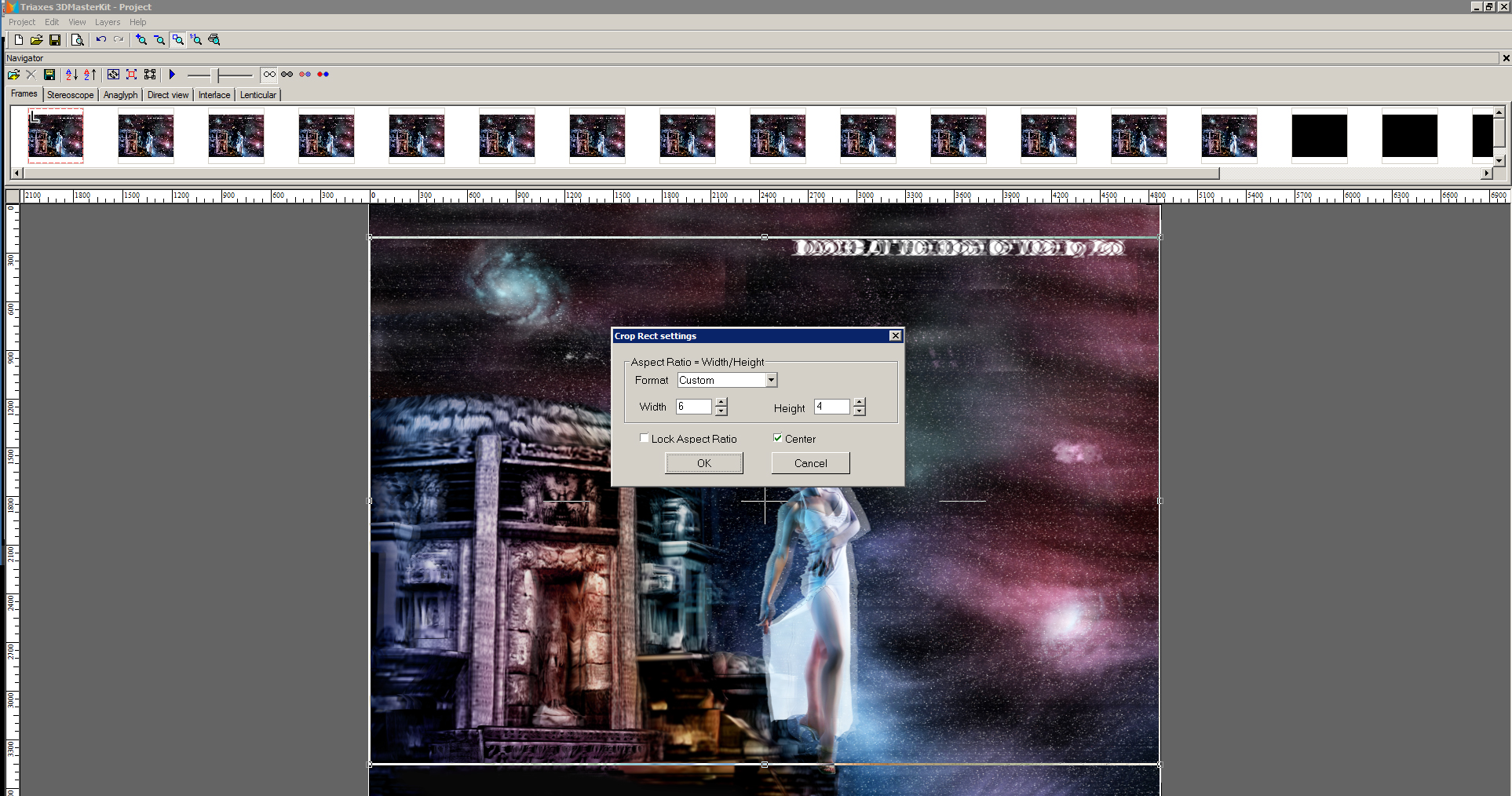
4. Use 3DMasteKit to create the lenticular final image.
The first thing to do is to crop the image. Select EDIT from the top menu and then input 6 inches wide by 4 inches high. See my screen image below!
The next step is to select LENTICULAR, Look along the second row of the top menu and click on LENTICULAR.
Check the size to confirm it is 6 inches by 4 inches. Make sure 600 DPI is selected and enter 60LPI in the Lens pitch box. Now we are not ready to print your image yet. Although the Event Frames are made as 60LPI, the manufacturing process for such detailed and refined acrylic can vary from batch to batch. You need to do a pitch test to determine the precise number of LPI. The last lot of Event frames I received came out t 60.2 LPI and therefore I enter this number into the LPI box instead of 60.
I cannot stress enough how important this is! Just 0.2 LPI difference will mean the difference between success and abject failure. These are the parameters to enter for your first test. See the image below.
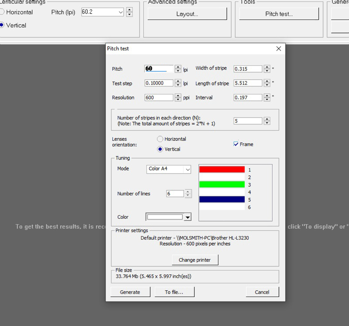
Print to paper (the paper you will use to print your images – (photopaper). The result (shrunk here to fit this page) will look like this., after you turn the print 90 degrees…
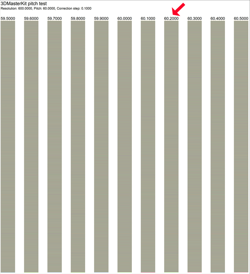
Each column represents a lens pitch differing by 0.1 lpi. Lay your open event frame on the print out, ensuring it lines up precisely. Move your view up and down watching each column change colour. The single column that changes through each of the colours—red, blue, green, such that each colour occupies the whole column completely before changing to the next colour is the correct lens pitch of your event frame. My ones change colour correctly at 60.2—which you obtain from the column header.
Creating the pitch test will seem overly complicated by reading the last page but in practice, most of the variables and parameters are already there by default. You just need to adjust a few and once you know the accurate pitch of your lenticular event frame, you don’t need to do it again until you order another batch.
Enter the new and precise LPI (60.2 in my case), into the box where originally you had 60 lpi and generate your picture either as a .BMP file or a .TIF file. I normally use .TIF.
Open the resulting image in your editor and optimise it by brightening it slightly. The effect of using the lenticular sheets (event frames) reduces the light being reflected back from the image so making it brighter compensates for this. Print your picture, making sure the printer is set to 600 DPI and the correct paper. Do not print BORDER LESS! Print ‘Bordered’!
Cut the 6×4 inch image from the A4 paper.
[box type="note"]Make sure you cut your picture accurately, square and parallel sides! I use a sliding paper cutter to get good results.
Pop it in the event frame and image are not squared together properly. Readjust until perfect (fiddly but do-able). And carefully apply the silicon stretchy band to the very top to keep the ftame firmly closed and thus the image pressed evenly to the back of the lenticular sheet.
Hopefully, you are looking at your first home-made Lenticular image and feeling that proud ‘WOW!’. If not, check to see what small error you made and try again. In the beginning, it took me a good few goes to see what small errors I was making but once you get it going, you’ll have no problem. It’s no good producing a finished picture in a frame for you here as you will not see the 3D effect. However, if you wish me to send you an example, I can do so at a small cost of £15.00 plus whatever the postage is: £3.75 UK and £6.50 USA. I don’t wish to make money out of club members but creating examples is a bespoke task and time consuming, which also involves the material costs as well. You can email me first to make sure I have frames here and how to pay etc., molsmith@fastmail.fm
I hope be able to provide the raw materials in small numbers, Event Frames, by the time you read this.
I have also created 10 sequence animations by taking 10 stills from home movies etc., using the 3D event frame and the software covered in this article. One needs to turn the frame around into portrait mode and the lenses go across the short side. To see the animation you tilt up and down instead of left to right. Flip images can be done as well but the effect is better done not with 3D (curved lens) frames, but FLIP (pyramid shaped lenses). Yes, it seems quite difficult at first , mostly due to errors one makes with using several software packages, materials, printers and trying to get everything to match 100%. Less than that ends with failed effects. But once you work through it all, it works! I wish you every success.
Mol Smith. www.3d-art.net & www.molsmith.net 2oth Feb. 2022


