
3d dimension of the photograph, Part 2
While you are viewing a stereo pair (or a multi-frame lenticular image), your left eye sees the left image of the stereo pair, while you right eye sees the right image. Thus, the situation of observing a real world with two eyes is modeled. However, viewing a stereo photo has one important difference: eye accommodation takes place on the plane of the picture (image media) and the stereo effect occurs only due to convergence. This artificial separation of vision mechanisms produces an unexpected result: the stereo effect is perceived better than in real life and produces a stronger impression. It happens because the human eye is focused on the object of your attention while observing the real world. This makes the background and the foreground seem blurred. On the contrary, while viewing a stereo photo (taken with a greater depth of field), everything seems clear in the scene.
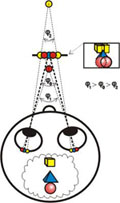
Fig. 1. Three-dimensional image reconstruction
The scheme of stereo perception is shown in Fig. 1. While you are viewing a stereo photography, the following happens:
- objects with zero parallax are seen at the convergence angle φ0 and are perceived as located on the key plane (the blue dot on the picture);
- objects having negative parallax in the image (red dots) are seen at the convergence angle φ1 and are perceived as located in front of the key plane;
- objects with positive parallax (yellow dots) are seen at the convergence angle φ2 and are perceived as located behind the key plane.
The nature of this phenomena lies in the ability of the eye-brain system to process information within some range Δφ (Δφ=φ1–φ2) of the convergence angle and merge conjugate images into one three-dimensional image. The maximum Δφ range is several degrees. If the parallax of the images in a stereo photo exceeds the abilities of the brain to merge images, it becomes less comfortable to view the image and you can see it double. That is why it is important to correctly choose a stereo base when you take stereo photos.
Methods of viewing stereo images
The creation of a stereo pair requires a method for display, of which there are several. Let us take the most popular ones.
Stereoscope
Fig. 2. Slide stereoscopes (picture from www.stereoscopy.com)
Probably, it is the most “ancient” device for viewing stereo photos. Its effect is simply based on placing the left image before the left eye and the right image before the right eye. Stereoscopes of various modifications are widely available and used to view stereo slides (Fig. 2).
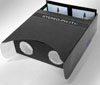
Fig. 3. Stereoscope (picture from www.stamptex.pl)
Wide capabilities are available with a stereoscope designed for viewing stereo pairs printed on paper (Fig. 2). This method is convenient because stereo cards can be easily made at home and if you do not have a stereoscope, you can view them as regular photos.
Due to the fact that the left and right images are distinctly separated and that it is possible to adjust the viewing distance, stereoscopes provide a beautiful stereo effect and comfort while you are viewing images.
Parallel/Cross-eyed viewing method
This viewing method requires no special devices but you need some training for your eyes. This method is based on setting your eyes to such an angle of sight line convergence that the left eye sees the left image while the right eye sees the right image.
If you use the parallel method, stereo pairs are located in front of your eyes in the order they were taken (Fig. 4-left image) and if you use the cross-eyed method, they swap places (Fig. 4-right image).
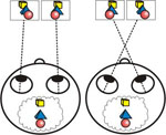
Fig. 4. Parallel and cross-eyed viewing methods
Training your eyes plays an important role: some readily see stereo images using the parallel method, some find the cross-eyed method easier. The size of images and the viewing distance are also important. It is obvious that it will be easier to view images at the distance of 40-50 cm if the distance between the centers of stereo pairs is not larger than the distance between the viewer’s eyes.
In Fig. 5, you can see a stereo pair for the parallel viewing method. To be able to see the stereo effect, you should look “through” the picture as if you watch an infinitely distant object. The sight lines of your eyes will be almost parallel, while the accommodation should be adjusted to the actual distance to the image.

Fig. 5. A stereo pair for the parallel viewing method (source images by Piotr Nawracala)
In Fig. 6, you can see a stereo pair for the cross-eyed viewing method. To be able to see the stereo effect, you should look at an imaginary object in front of the image, the sight lines will intersect in this case and the accommodation should be adjusted to the actual distance to the image.

Fig. 6. A stereo pair for the cross-eyed viewing method (source images by Piotr Nawracala)
Anaglyph method
White light consists of the combination of electromagnetic waves of all visible lengths – it was first described by Sir Isaac Newton in Optics (1704). He discovered that a glass prism separates white light into a spectrum of colors and brings this spectrum together into white light again. The approximate wavelengths of spectral colors are given in Table 1.
Range (nm) |
Color |
|---|---|
| 380 – 450 | Violet |
| 450 – 490 | Blue |
| 490 – 560 | Green |
| 560 – 590 | Yellow |
| 590 – 640 | Orange |
| 640 – 730 | Red |
Table 1.Approximate wavelengths of spectral colors
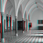
Fig. 7. Monochromic anaglyph image of a stereo pair (source images by Piotr Nawracala)
The anaglyph method (from the Greek word anagliphos, meaning embossed) is based on adding complementary colors to images in a stereo pair. The colored images are shown (printed) as superimposed over each other. Red and cyan colors are used most often. It is convenient because these colors are located on the opposite sides of the spectrum, which makes it somehow easier to separate them. Besides, red, blue and green are primary colors. i.e. the combination of these colors can give us the rest of colors in the complementary model.
You can see an example of an anaglyph image in Fig. 7. On those parts of the photo where the brightness of both images is the same, you can see white color of various brightness (gray, black); but on those part where it is different, you can see doubling in complementary colors. These doubling results from the difference in the images taken from different points and it creates the three-dimensional effect.
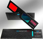
Fig. 8. Glasses for viewing anaglyph photos (picture from www.stamptex.pl)
The separation of the left and right images happens when you view an anaglyph image through color glasses (Fig. 8).
The red glass lets only the light with the red color wavelength through and the blue glass lets only the light with the blue and green color wavelength through. As a result, the left eye sees only the left image with red color added to it while the right eye sees only the right image with cyan color added to it. The brain processes the signals and creates a three-dimensional image.
There are methods that produce anaglyph images and allow you to keep nearly all of the original colors of the source stereo pair. However, if there are bright red or bright blue (green) objects in the source images, it may influence the correct separation of the stereo pair in a color anaglyph. As a result, these objects will make viewing the image uncomfortable. You can see three types of anaglyph images of one and the same stereo pair below: the monochrome anaglyph produces a good stereo effect no matter what original colors are, quasi-colored anaglyph also looks good, but flags and other red objects start “catching your eye” in the colored anaglyph.
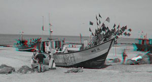
а) monochromic anaglyph

b) anaglyph with partially kept colors (quasi-colored)

c) colored anaglyph.
The computer monitor is a wonderful way to display anaglyph images because the RGB color model used to produce color on screen is vivid and complimentary colors such as red and cyan are by their nature opposite to each other. When anaglyph images are output to paper they use a different method for creating color, the subtractive CMYK model. Sometimes it is difficult to print anaglyph images because colors are reproduced according to the subtractive principle and there is no strict correspondence between the additive and subtractive color models.
LCD glasses
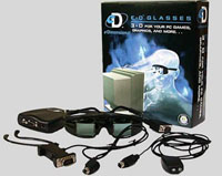
Fig. 9. Liquid crystal shutter stereo glasses and connection accessories (picture from www.really.ru)
This method is most often used to view images on the computer display, but it can be also used to view stereo image projected on the reflecting screen. It is based on the following principle:
- the viewer puts on glasses with liquid crystal elements inside them, these elements can become opaque when they receive a signal;
- the right and left images are displayed on the screen in turns. The frequency of changing images should be high enough (not less than 60 Hz) for the viewer not to notice the flickering;
- synchronously with images displayed on the screen, liquid crystal shutter glasses stop the light flow for the left and right eyes in turns.
- Glasses are controlled with synchronous impulses that can be transmitted either by cable or using a wireless method.
You can see the liquid crystal shutter glasses “E-D glasses” manufactured by eDimensional, Inc (www.edimensional.com) in Fig. 9.
Lenticular screen
Fig.10. Lenticular screen (picture from www.stamptex.pl)
This method is based on the idea to combine the device for separation of stereo pairs with the image media. It allows one or several viewers to see a stereo effect without additional tools.
Professor Gabriel Ionas Lippmann (1845-1921) from the Paris University offered to use an optic lenticular screen to create stereo images. Maurice Bonnet, a French photographer and inventor, managed to realize this idea in practice first. He developed a technique and a special camera for multi-frame shooting.
The principle of producing a stereo image with a lenticular screen is based on the following: an image that has been prepared in a special way (let us call it encoded) is covered with a plastic sheet (or plate) the front surface of which consists of a great number of parallel cylindrical lenses (Fig. 10). These lenses usually have a small width that is invisible to the viewer.
Fig.11. Part of the encoded image
The encoding of images in a stereo pair means “cutting” the source images into thin stripes and mixing them in such a way that a pair of stripes is located under each lens: one from the left image and the other from the right one. Preparing an encoded image was a difficult task for a long time and required special equipment and skills. Currently this operation can be carried out with the help of the computer, which makes the process of making a high quality lenticular stereo image much easier. In Fig. 11, you can see a zoomed part of the encoded image of the stereo pair shown in Fig. 5.
Light reflected by the encoded image passes through lenses and thus gets separated in such a way that the left eye of the viewer sees the left part of the stereo image, while the right eye sees the right part (Fig. 12).
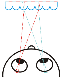
Fig. 12. The diagram showing how the encoded image of a stereo pair is separated by a lenticular screen. The left image is shown as red and the right image is shown as blue.
The strongest effect of the lenticular stereography can be achieved if you encode not two images of a stereo pair, but a few additional images from between them (for example, 12 images). In this case, there appears a large stereovision zone and the viewer sees the scene change, which creates the effect of looking around. It becomes possible to take a look behind the objects in the foreground. It makes the stereo image being viewed look natural.
You can also use a lenticular screen to create various “animated” images. If you encode different images (e.g. a sequence of frames from a cartoon), the lenticular screen will show different source images while you are viewing the image at different angles. Thus, you can play a sequence of images by smoothly changing the viewing angle.


