5.2 Depth map creation from a stereo pair
- Choose «Stereo pair» in the Select source images type (Fig. 5.5)
Menu command: Project | New, hot key Ctrl+N
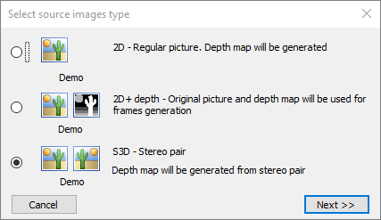
Figure 5.5 Select source images type dialog
Press Next >> - Open source images dialog will appear.
- Select and open the left and the right frames of a stereo pair in the Open source images dialog (Fig. 5.6).
First, open the source image. It should be the left image of a stereo pair or side-by-side double image. For example, "C:\Program Files\Triaxes\StereoTracer-en 10.x.x\samples\Stereopair\Flower_white_sp.jpg". Preview of the chosen image will be shown in the left window of the dialog under the sign “Left image”. Then click Split to get the right frame in the "Right image" preview.
If the right image of stereo pair is located in a separate file, press the left mouse button on the right dialog's window under the sign “Right image” and select that file. For example, "C:\Program Files\Triaxes\StereoTracer-en 10.x.x\samples\Stereo pair\white_flower_R.jpg" (Fig. 5.6). Press Open.
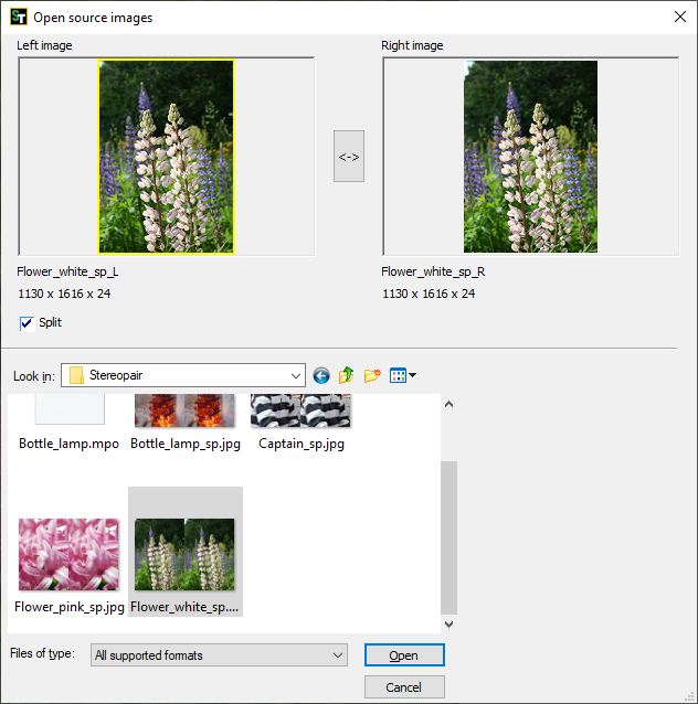
Figure 5.6 Open source images dialog
- Select outcome dialog will appear:
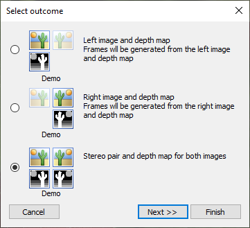
Figure 5.7 Select outcome dialog
It’s possible to get 3 variants of the outcome, which will be used for multiview series generation:
- the left image and a depth map for the left image
- the right image and a depth map for the right image
- a stereo pair and depth maps for both images
Select the outcome type and press Next >>.
- The left and the right frames of a stereo pair, overlapped upon each other are represented in the Matching of images dialog (Fig. 5.7.). It’s possible to carry out matching of images automatically or manually. Use Auto parallax button for automatic matching. To match frames manually, use the sliders. Match the left images by the most distant object and the right one by the closest object, thus, to obtain the max sharpness of the object, by which the matching is being done.
Press Auto align button to align the frames vertically in the automatic mode. Vertical alignment provides that one and the same object in these frames will be on the same level. This is an obligatory condition of getting better result.
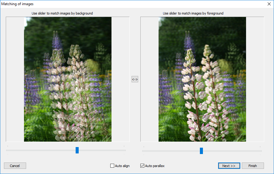
Figure 5.8 Matching of images dialog
- There are 9 different variants of the depth map In the Select depth map dialog (Fig. 5.9), from which it is necessary to select the best one (usually it’s the central variant). Note, that it’s just a preview mode. The quality of depth maps in the preview mode is lower than it will be after the selection.
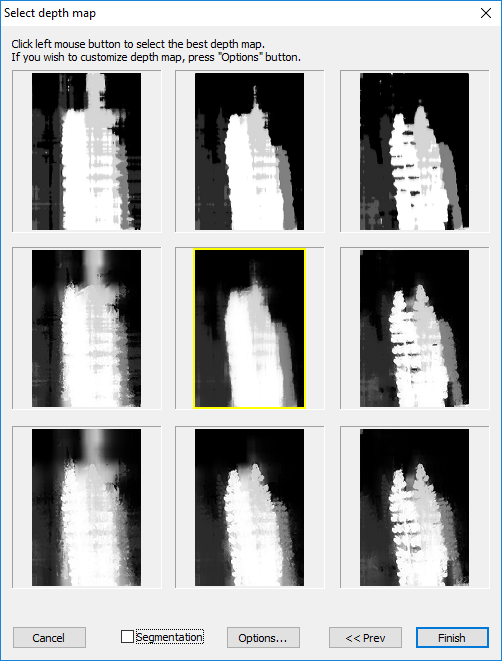
Figure 5.9 Select depth map dialog.
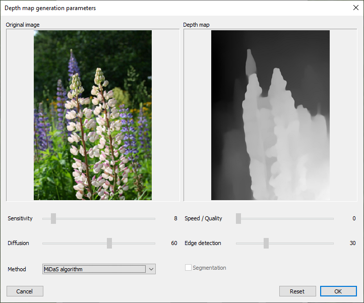
Figure 5.10 Depth map generation parameters dialog
It is possible to change depth map generation parameters in Depth map generation parameters dialog (Fig 5.10), which opens by pressing the Options… button in the Select depth map dialog (Fig. 5.9).
If your StereoTracer version supports a depth map generation module using the MiDaS algorithm (starting from version 10), then this method will be selected by default for a depth map generation in this dialog. You can choose one of two methods: Standard ST parallax or MiDaS algorithm.
- Press Next >> after the variant of a depth map is selected – the process of a depth map generation will start. (Fig. 5.10.).
Figure 5.11 Depth map generation progress bar
- The result, which will be shown in the main window, depends on the outcome variant, you’ve selected in Select outcome dialog (Fig. 5.7). In case of selection you select “left image and depth map for left image” or “right image and depth map for right image” you will see an image (left or right) with the corresponding depth map (Fig. 5.12)
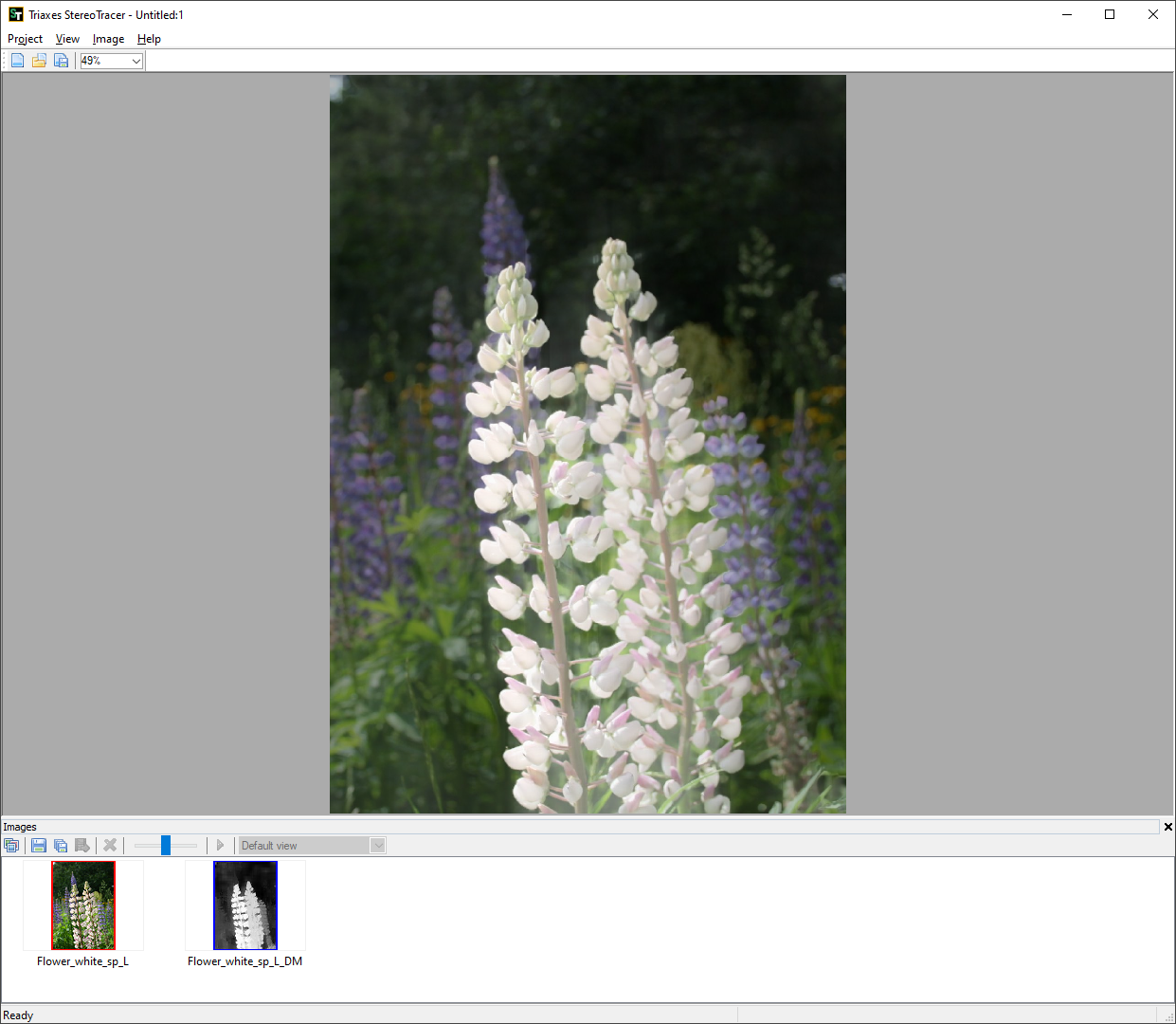
Figure 5.12 Main window
In case of selection you select “stereo pair and depth maps for both images” you will see the left image with the left depth map and the right image with the right depth map (Fig. 5.13).

Figure 5.13 Main window
The left image with the left depth map and the right image with the right depth map are represented sequentially in the Images window. Left image and left depth map (or right image and right depth map), overlapped upon each other, are represented in the main window. Use the slider of the Images window to compare an image and its depth map.
Now, you can generate a 3D sequence of frames as it was described in section 5.1, steps 4 and 5.
There is the only difference in generation process namely Frames generation options dialog. In case of selection you select “stereo pair and depth maps for both images” you’ll get:
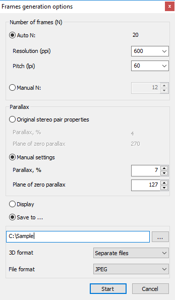
Figure 5.14 Frames generation options dialog in case of selection “stereo pair and depth maps for both images”
It is possible to set the following parameters of generation:
1) Number of frames is the number of frames, which will be generated. There are two options for setting the number of frames: automatic calculation (Auto N) or manual input (Manual N).
For automatic calculation you must input the parameters or choose 2 parameters from the list depending on the future printing settings: printer resolution (ppi) and lens pitch (lpi). In this case number of frames (N) is calculated as follows:
N = k * R/L,
where “k” is the correction coefficient that equals 2, "R" – printer resolution (ppi), "L" – lens pitch (lpi). Using this coefficient enables to refine the image of objects with the big parallax values (usually these are foreground and background objects).
For the manual input - the frame number limit is 1024.
2) Select, what the set of parameters you will use for generation:
- Original stereo pair properties are parallax and plane of zero parallax values, calculated automatically from the original stereo pair.
- Manual settings are parallax and plane of zero parallax values, you can set manually.
Parallax is the value, which characterizes the distance of the object's projections on the plane for the left and right eyes (disparity). It’s specified in percentage from canvas width.
Available range: from the original parallax value to 25.
Default value: 7.
The bigger value corresponds to the bigger 3D effect, but it should be taken into account that the value bigger than 10 often causes artifacts on the generated images. So, we recommend to use values from 5 to 10.
Plane of zero parallax characterizes the placement of the zero parallax plane.
Available range: from 0 to 255.
Default value: 127.
For 255 value the plane of zero parallax (disparity) is situated at the foreground (at the depth map the foreground is colored in white), while the whole image is situated in the depth. For 0 value the plane of zero parallax is situated at the background (colored in black), and all of the image's objects seems to be flying above the paper or screen. Usually the best results can be achieved with the values in the 100-160 range.
3) Select: Generate frames to display in the program or save frames as files to disk:
- Folder path - press "..." to select the folder on the computer;
- 3D format - save frames as separate image files or single image with 45 frames using for Looking Glass 3D Display. The image has 9 rows and 5 columns with frames. The first frame of sequence located in the bottom left corner of tile image;
- File format - you can choose one of the several standard raster image file formats: JPEG, PNG, TIFF, BMP. The default file format is JPEG.
Using this option you can save images as files on the hard drive when you work with big-size images or a big number of images, or when there is not enough RAM for the software to buffer images.