4.1 Making a lenticular flip photo
Lenticular flip images and Legend
Images which change depending on the viewing angle, are commonly referred to as lenticular flip. Lenticular flip images consist of two or more frames. In the simplest case, only two different frames are used. The encoding means “cutting” frames into thin stripes and mixing them in such a way that a pair of stripes is located under each lens: one from the first image and the other one from the second image.
The flip effect is achieved due to changes in the viewing angle; movement causes lenses on the lenticular screen to single out one or the other source frames from the encoded image (Fig. 4.1).
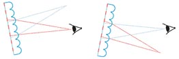
Fig. 4.1. The operation principle of the lenticular flip image
(the first frame is red, the second one is turquoise)
We need two frames to work with.
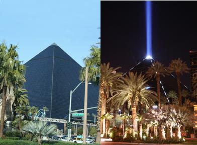
Fig. 4.2. Source frames
Some slogan will be required. Using Photoshop we cut the inscription out of another photo and save it with the transparent background into a separate file.
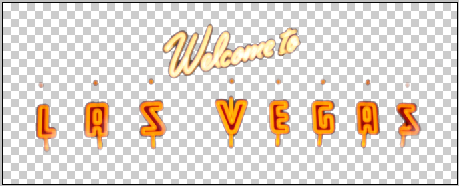
Fig. 4.3. The slogan for the card
We start by launching Legend and load frames by selecting the Project >> Add frames command (hot keys: Ctrl+Shift+O).
Then we select files with photos and move them to the right list in the Open source images dialog by clicking the button with an arrow to the right.
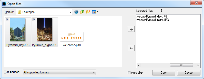
Fig. 4.4. Open source images dialog
After you click Open, the photos will be displayed on the list of frames at the upper part of the program window in the Frames tab of the Navigator window (Fig. 4.5).
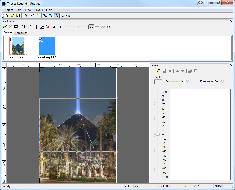
Fig. 4.5. Navigator window
The frames will be automatically set as the Left and Right ones and marked with the red and the blue dashed rectangles correspondingly. Both frames will be shown in the main window of the program. The Right frame will be automatically made Active and superimposed over the Left one with transparency. That showing method is for comfortable setting of the relative position of frames on a ready flip image.
You can move the image with the left mouse button by dragging it to the place where you need it to be (fig. 4.6). You can position the image precisely using arrow keys on the keyboard (left, right, up and down).
Note: To select the image you want to edit, click on it on the list of frames.
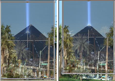
Fig. 4.6 Image movement
A photographer held the camera in his hands while taking photos and one of the frames turned out to be a bit askew. We can see this situation in the Pyramid day image. Legend allows the situation to be corrected. Execute the Edit >> Rotate command and use your mouse to specify the necessary rotation angle (fig. 4.7).
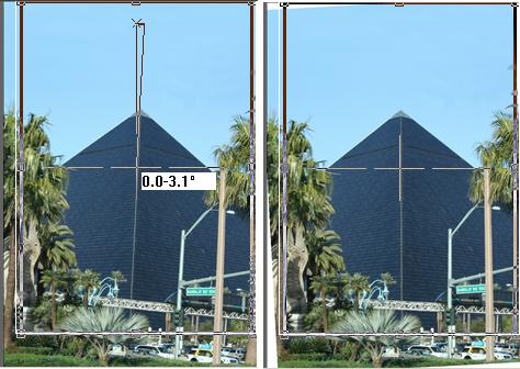
Fig. 4.7. Frame Rotation
Legend can also scale images (menu command Edit >> Transform >> Scale), which allows you to match the size of objects if necessary.
The next step is to add the message to the picture.
Use the Layers >> Add command and select the file with the text image.
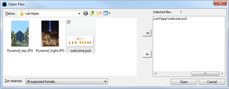
Fig. 4.8. Adding layer with the text image
After the transparent layer with the text is added to the project, adjust its size and position.
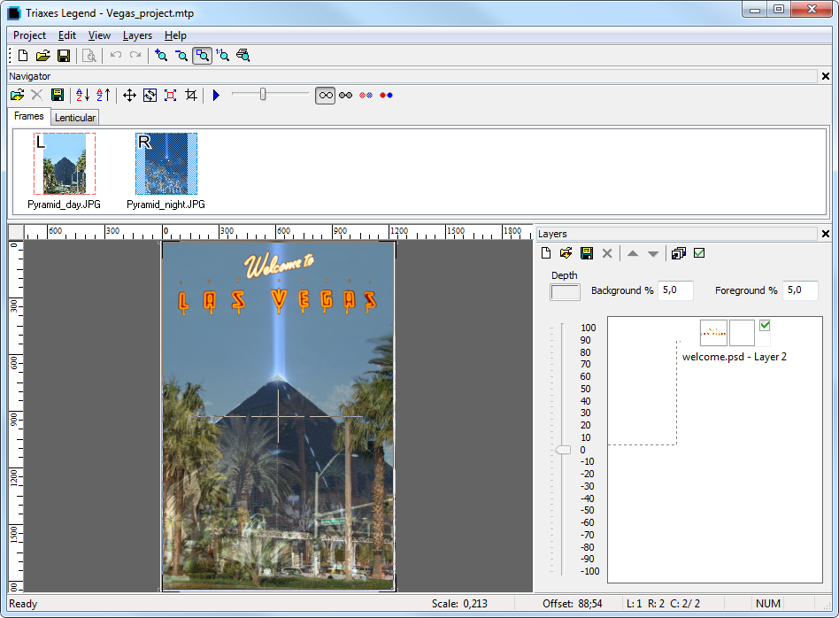
Fig. 4.9. The image with overlapped text
Then it is necessary to generate stereo frames from layers (Alt+G), but in the Overlapping existing frames mode (fig. 4.10). In this case frames generated from layers do not replace the existing frames, but overlap them.
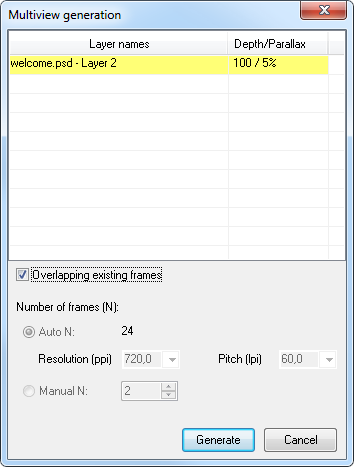
Fig. 4.10. Overlapping existing frames mode
The working area of Legend always contains the Crop Rectangle control element (it looks like a rectangle with active areas in its corners). It automatically detects the area of image overlapping allowing us to select the area of source frames that will be present in the final photo. In other words, it shows the area that will be included in the final image. The frame can automatically keep the aspect ratio you need. Suppose we are going to prepare a photo with the size of 10x15 cm. Open the Crop Rect Settings dialog (Edit >> Crop Rect Settings), specify the image proportion you need and also select the Lock Aspect Ratio checkbox (fig. 4.11).
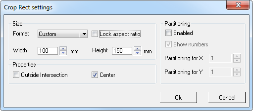
Fig. 4.11. Crop Rect settings
The active areas on the sides of the rectangle allow you to change its size keeping the aspect ratio. Use this tool to crop the image in order to remove the unneeded background.
As a result, the frame will look as shown in fig. 4.12.
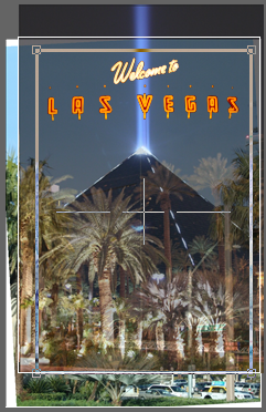
Fig. 4.12. Cropping source images
Now you can start encoding the images. Open the Lenticular tab of the Navigator window. This tab shows control items that allow you to specify the size and resolution of the encoded image, lens orientation (horizontally or vertically), lens pitch (encoding pitch) and generation method. To create a lenticular image, select the horizontal lens orientation (fig. 4.13). In the same dialog you can create a test allowing you to select a precise encoding pitch for particular lenticular lens - Pitch Test button (see Correcting the encoding pitch in section 2.10 ).
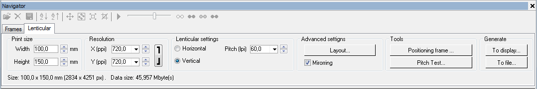
Fig. 4.13. Settings of the lenticular lens encoding
Note! Printing on the lenticular lens is performed on the back of the lens, therefore it is necessary to mirror the encoded image. Most plotters for direct printing have special printing software for printing process control. Triaxes Legend is intended to generate the encoded image for viewing via lenticular lens. If you are not going to mirror the image with special printing software, do not forget to mark it with a tick
Mirroring before encoding.
When all the necessary settings are done, click on one of the generation buttons and you will see the encoded lenticular image on the screen in a few seconds (fig. 4.14).
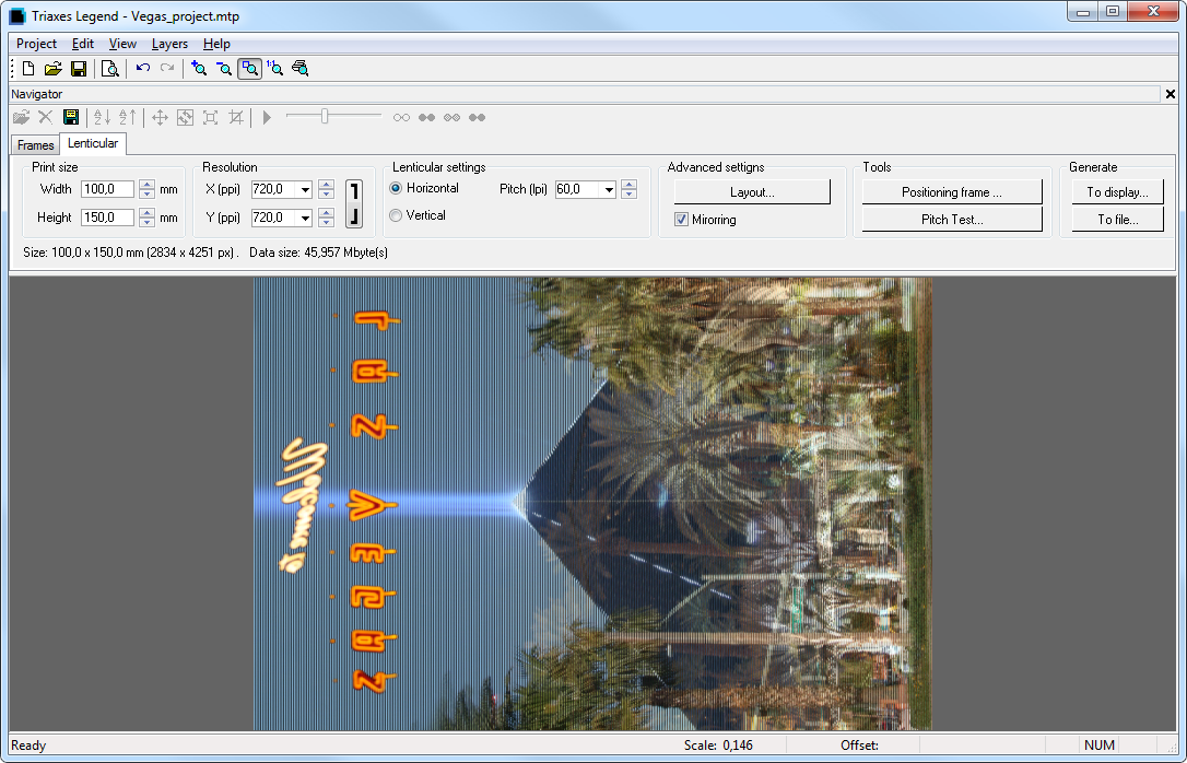
Fig. 4.14. Encoded lenticular photo
You can see the enlarged part of the encoded image in fig. 4.15.
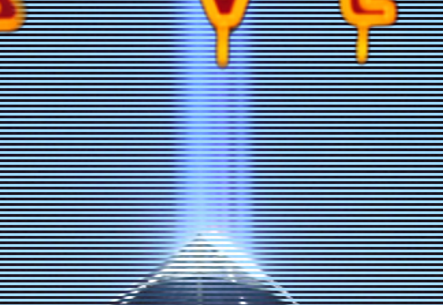
Fig. 4.15. The enlarged part of encoded image
Now you only have to print the image and attach the lenticular screen. Select the Project >> Print preview command and Legend will show you the image in the position it will be located on the sheet of paper (fig. 4.16). Using the input fields or by dragging the image with the mouse, you can specify the necessary position of the photo on the page. You can also rotate the image to 90 degrees and also fill the page with copies of the image. The Print setup button allows you to specify the page size and printer parameters. The Print button sends the image to the printer. Print the image and cut it out of the sheet of paper.
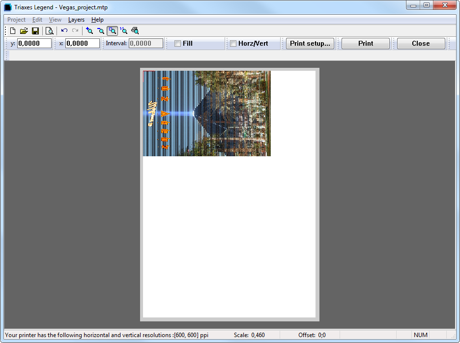
Fig. 4.16. Print preview
Applying lenticular screen
Lenticular screens are attached to paper by means of the cold lamination. First, a lenticular screen is covered with an adhesive layer that has a protective transparent film. When you attach it, the protective film is removed and the lenticular screen is attached to the paper. It is best to use a laminator that supports the cold lamination function. Before attaching make sure that you orient the lenticular screen in such a way that its lenses are parallel to stripes of the encoded image. A good lenticular effect is achieved when the pitch of the encoded image coincides with the pitch of the lenticular screen and when the encoded stripes are parallel to the lenses of the lenticular screen.
1. Fold up about one centimeter of the protective film:
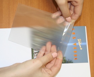
Fig. 4.17. Fold up 1 cm of the protective film
2. Apply the smooth side of the lenticular screen to the image making sure that the opened adhesive layer does not touch the paper.
3. Press the covered part of the lenticular screen to the image and watch the moire effect that appears due to the interference of the stripes of the encoded image with the lenses of the lenticular screen (fig. 4.18).
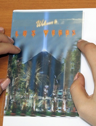
Fig. 4.18. Applying the lenticular screen to the image
Slightly rotate the lenticular screen relative to the paper to remove the moire effect (fig. 4.19). A special tuning frame around the image helps to orient the lenticular screen correctly.
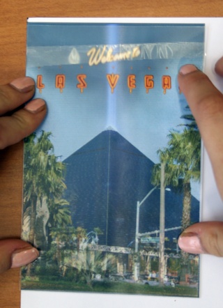
Fig. 4.19. Orienting the screen
4. Changing the viewing angle back and forth along the direction perpendicular to the direction of the lenses of the lenticular screen, check how precisely the images replace each other (fig. 4.20).

Fig. 4.20. Precision of the images changing
5. After you align the position of the screen, carefully press the opened adhesive layer to the paper:
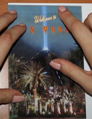
Fig. 4.21. Pressing the adhesive layer to the paper
6. Turn on the laminator (in the cold lamination mode or with a minimal heating – to remove bubbles). Hold the turned-up side of the protective film:
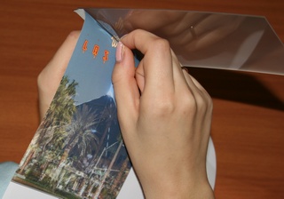
Fig. 4.22. Holding the film
Run the lenticular screen through the laminator removing the protective film as the screen is moving:
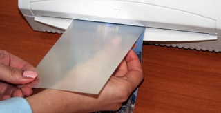
Fig. 4.23. Lamination
Now you only have to cut off the superfluous screen or paper on the sides of the image. This operation is required only if the size of the screen exceeds the size of the photo or vice versa.
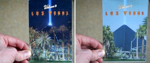
Fig. 4.24. Finished lenticular photo