2.8 Lenticular image creation
Legend software allows you to prepare images for viewing through the lenticular screen.
To create this kind of images do the following:
- Create a new project or open an existing one;
- Add a multi-view sequence of frames to the project. Sort frames on the list so that they are located in the order of shooting from left to right;
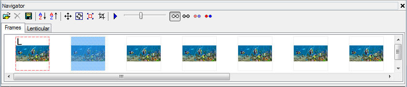
Fig. 2.5. Navigator window. The sequence of frames
- By means of the context menu which opens by the right-clicking set the leftmost frame of the series as the Left frame and the rightmost one as the Right frame. Perform alignment of the Left frame with the Right one by a chosen object, which will be located at the zero parallax plane. Then execute the Edit >> Automove menu command. As the result, all the in between frames will be aligned. After that, it is necessary to select all the rest frames in turn (make them Active), in order to make the final vertical and horizontal adjustment as well as zero parallax point adjustment, if it is necessary;
- If it is necessary to use only some images of the uploaded series (not all of them), for example, in order to decrease parallax of the scene, you can select a necessary sequence of frames by marking the outermost frames of the sequence as Left and Right ones;
- Crop images the way you like using Crop rect;
- Switch to the Lenticular tab in the Navigator window. Set the parameters of the lenticular material and print size then click Generate;
- The generated (interlaced) image can be either printed or saved to a file.
Useful tip: The program has a feature of saving to a file simultaneously with generating. It is convenient to use this feature when creating lenticular images of large sizes. The To file option allows you to significantly speed up the generating process. Besides, if there is not enough RAM to display the lenticular image on the screen, you can still create it with the help of the option of direct encoding to a file. The image is generated either to a Photoshop .psd file (with the support of the CMYK color model) or to the Windows bitmap .bmp format. Files with the image size of more than 30 000 x 30 000 pixels or with the size of more than 2Gb are saved in the Photoshop .psb or BigTIFF (.tif) formats intended for large documents. For more details see section 3.1 Working with a project – Encoding to file
The project can be saved as an .mtp file. All the changed settings will be saved in the project.
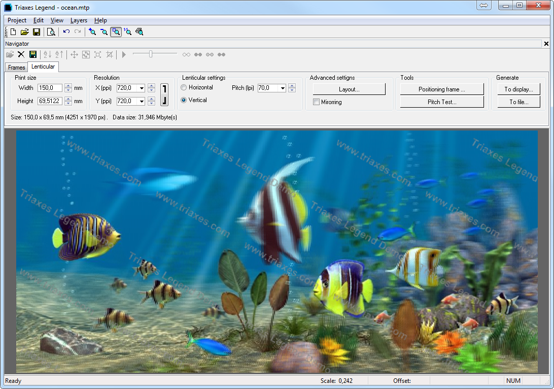
Fig. 2.6. Lenticular tab of the Navigator window (photos made by Andrezej Pędowski).
Encoding parameters
The Width and Height parameters allow to specify the image size (in millimeters) you want to use for printing. When you change the size, the image proportions are retained. You can change proportions by cropping the image using Crop rect (Frames tab).
The Resolution parameter defines a resolution of the encoded image in ppi (pixels per inch). In most cases it is recommended to set the resolution equal to the resolution of the printer you use in ppi. Note, that printing resolutions are indicated in dpi (dots per inch). Values, which are specified by printer manufacturers, can be up to 5440 dpi and more. However, it is necessary to distinguish the dpi resolution from the ppi resolution. When processing in the program, a digital image resolution is measured in ppi. When the image is printed, every pixel is represented by several color dots. That is why the printing resolution in dpi is higher than the digital image resolution in ppi. At the same time, printer driver processes images with the resolution defined in ppi. For Epson printers this resolution is usually 720 ppi, for Canon printers - 600 ppi. Use the Preview mode or the Pitch test dialog to find out the printing resolution in ppi.
Before printing the image, the program by request of the printer driver sets the image to the resolution (in ppi) which the driver is capable to process. So if you create an image for printing, you are advised to use the printer resolution in ppi. It would save both generation time and required memory size.
Note: The Resolution parameter has a direct influence on information transmission from the source frames sequence to the encoded image. When specifying the resolution, you should take into account that the higher the value of this parameter is the larger the encoded image will be (in bytes) and the longer it will take to encode it. On the other hand, small values set for this parameter will cause to detriment of image quality.
The minimal number of source frames can be calculated in the following way:
Nmin = Res/Pitch
Where Nmin is the minimal number of frames, which is needed to get a satisfactory 3D effect and Pitch is a pitch of a lens measured in lenses per inch (lpi). For example, if the resolution equals 720 ppi and the pitch is 60 lpi (Pitch=60), then Nmin is 12. So it is better to use at least 12 source images to create 3D in this case.
Image encoding can be performed for a lenticular screen with either horizontal or vertical lenses orientation. The direction of lenses is set in the Horizontal/Vertical option. You should set vertical direction of lens for stereo images (in respect to the horizon line). Dynamic images (flip, morph, etc.) can have any lens direction; however, most typically horizontal lenses orientation is used. The Pitch parameter defines the width of the lens base. This value is specified in lpi (lenses per inch). You can select the value from the drop-down list or type it using the keyboard.
Legend allows encoding an image part by part. It may be useful when you have to print a large format image. For more details see section Canvas and image cropping.
Useful tip: Sometimes when a lenticular screen is imposed on the printed image the color moire effect occurs (periodical stripes running over the image). This effect appears due to the interference of the lenticular lens with color dots of the image. The effect occurs when using printers with regular method of color dot formation. To reduce the moire effect, sometimes it is useful to rotate the image before printing. The rotation angle is defined in the following way: you must apply the lenticular screen onto the printed image and rotate it until the moire disappears. This angle can be measured with the protractor or using mathematical formulas (arcsin, arctg etc.). The rotation of the image to the appropriate angle during printing should prevent the color moire effect.
Rotate with the Rotate dialog.
Menu command: Edit >> Transform >> Rotate Precise
Hot keys: Ctrl+Alt+R
Toolbar button: ![]() .
.
Attention: To get a high quality lenticular image you have to perform a pitch test prior to encoding in order to correct the encoding pitch.
Picture layout
You can use additional settings for the encoded image: Alignment marks and Crop marks. The picture layout is created to demonstrate in the preview mode how these parameters are applied. To open the Picture Layout window press the Layout button in the Lenticular tab. The dialog with the picture layout parameters will be shown (see Fig. below):
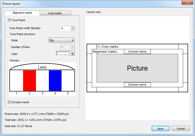
Fig. 2.7. Picture layout dialog
When enabling the Alignment marks option in the Alignment marks tab you can set the frame width measured in lenses (i.e. the width of 1 lens corresponds to a 1-stripe interval of the alignment frame). In the Alignment marks structure group you can choose one of the pre-installed modes for flip and 3D images, or the manual mode, where you can set the number of colored lines. You can also set the color for each line under the lens, for that - choose the required color in the palette and left-click on the required line in the Preview area (or use the right click when hovering on the line).
Note: To quickly color all the lines with the chosen color - hover on the rightmost or leftmost line, press and hold the left mouse button, then pass the cursor towards another utmost line and release the left mouse button when the cursor hovers on the required line.
The Dynamic marks parameter adds the area of dynamic marks to the upper and lower parts of the frame in the middle of its width, which helps to align the printed image under the lenticular lens. When the image is positioned correctly, the mark in the lower part of the area will be located right under the mark from the upper part of the area.
In the Crop marks tab the Crop marks checkbox allows to set the length of the crop marks (in mm/inches). The Outline frame parameter adds an outline black frame with the width of 0,1 mm (or 0,004 inch) to the resulting image.
In the Layout view area you can see the way the layout will look like with the current settings of the alignment marks, crop marks and outline frame. In the left lower part of the window you can find the image size (in mm/inches and pixels), current overall size (with the width of the alignment frame and the crop marks), as well as the output file size when you generate the image to a file. Below you can see the image generated with the use of all the above mentioned encoding parameters:
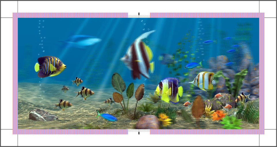
Fig. 2.8. Alignment marks and crop marks for the encoded image
Correcting the encoding pitch
To get a high quality lenticular image, the pitch of the lenticular screen has to precisely match the width of encoded stripes in the image.
To identify the precise encoding pitch it is necessary to perform a pitch test prior to the encoded image generation. The pitch test is conducted once for every printer type, for every paper type, for every type of printer settings and for every lens type.
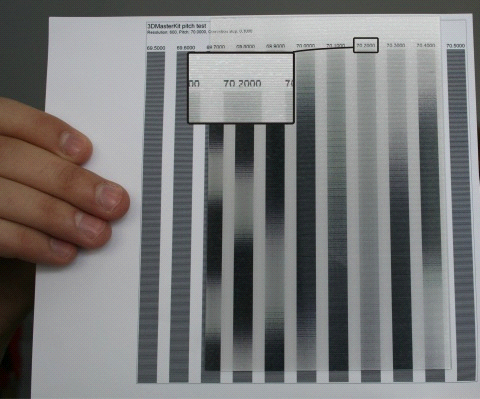
A fragment of the pitch test is shown in the picture (fig. 2.9). The test represents a set of stripes, each of which contains coded lines which have their own pitch different from the neighboring stripe by the value of the Correction step. To find out the necessary value of pitch correction, you should print the test using the printer and paper on which you are going to print the encoded image.
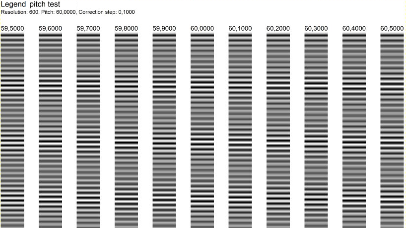
Fig. 2.9. Lenticular pitch-test
To generate the pitch test, you have to switch to the Lenticular tab of the Navigator window and press Pitch test. After that, you will see the Pitch test dialog as it is shown in the Fig. below. You can specify the necessary parameters of the test page in this dialog.
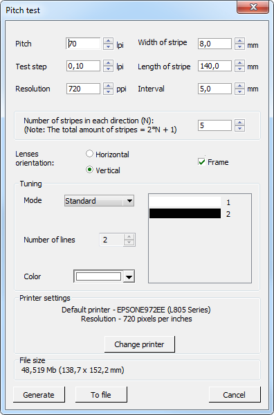
Fig. 2.10. Pitch-test generation dialog
The value of the tested pitch is set in the Pitch field and is specified in lenses per inch (lpi).
The distance between lines in each stripe can be specified in the Test Step field. As a rule, at first the step value of 0.1 is tested, the stripe which renders switching between background colors more precisely and sharply is kept in mind. After that a refining pitch test is performed with the step of 0.01 lpi.
Use the Resolution field to specify the printer resolution (in ppi). It is recommended to enter the resolution which will be used to encode the lenticular image.
Besides, you can set the stripe length and width, the quantity of stripes and the distance between them, as well as direction (horizontal or vertical), printer resolution and the color of the background and lines constituting the stripes.
The Frame checkbox allows the lenticular screen to be applied correctly to the printed pitch test. A pixel-wide frame is placed around the pitch test, which allows it to be aligned with the lenticular screen appropriately. To perform this, apply the lens to the pitch test in such a way so that the black frame is visible at a certain angle throughout one lens along the full length.
Click Select printer to choose one of the installed printers in the system. The Printer name and its resolution (pixels per inch) will appear above the button.
By clicking To File you can save the generated pitch-test into a file.
The File size field will show the generated file size (raster data) or a prompt error message will appear if there's some input error:
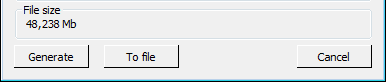
Fig. 2.11. File size field in the Pitch-test generation dialog
The Pitch test generates in three modes: Standard, Thin, and Custom.
Standard mode generates two lines with a 1:1 aspect ratio for every lens. On default one line is black, another one is white.
Thin mode generates N lines with the size of 1:N size, where N is determined by the following correlation: (Resolution) / (Pitch). On default the first line is black, the others are white. This handy mode enables to determine the real printer resolution, as well as the visibility of a separate frame.
Custom mode allows to control the number of lines in a stripe.
You can set the color by double left-clicking or right-clicking on the line image, or choose the required color in the palette and left-click on the line. You can also change the color of all lines or a group of lines by selecting them with the mouse.
You can type the number of lines directly in the Lines number field or change the value by 1 unit up or down using the corresponding arrows.
The stripes on the test sheet are numbered, and there is a specified line-repetition interval for each stripe (analog of the lenticular pitch).
To find the best pitch for lenticular encoding you have to:
1) apply the lenticular material to the test sheet (with the smooth side) so that the strokes of test stripes match the lenses;
2) look at the lenticular image so that the view direction is perpendicular to the lens orientation, view the image from the distance optimal for image observation (30-50 cm for images with the width of 10-30 cm, 1 m – for large-width interior design items);
3) by altering the angle of observation (moving forward and backward in respect to the lenticular image) identify the code stripe which changes its color simultaneously along its full length. Use the pitch period of this stripe when encoding the image - enter the pitch value into the Pitch field (lpi).
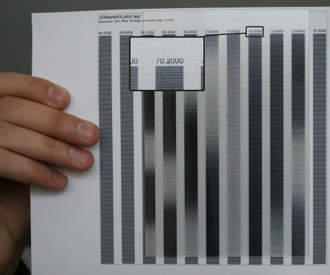
А |
Б |
Photos A and B show identification of the proper pitch for lenticular lens of 70 LPI. The optimal value is determined as 70.2 LPI. |
|
For more information read this guide: Pitch-test.