In order to create a stereo-image from some ordinary picture we have to do the following (see also section 2.13):
- Launch 3DMasterKit, open a multilayer template and a photo;
- Arrange template elements (layers) and a picture on a canvas the way you like;
- Set foreground and background parallaxes values;
- Locate layers and a photo according to their depth using relative depth scale;
- Give a command to generate a sequence of stereo-frames;
- Encode a stereo photo of any type: lenticular, anaglyph, etc.
A set of multilayer templates created by professional designers, is included in 3DMasterKit software package. Templates can be seen on triaxes.com, «Templates» page.
Start by launching 3DMasterKit and loading frames as layers by selecting the Layers >> Add menu command (hot keys: Alt+Shift+O).
In the Open Frames dialog select files containing the photo and a template, and then move them to the right list by clicking the right arrow button (fig. 4.25).
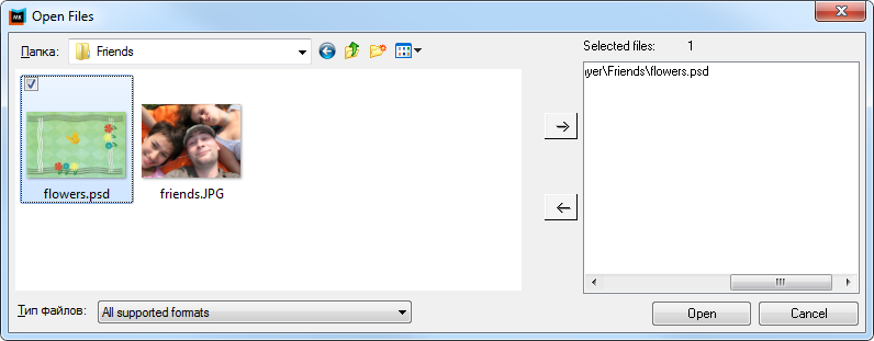
Fig. 4.25. Open layers dialog.
After the Open button is clicked, a photo and template layers will be displayed in the layers list, on the right side of the screen (fig 4.26).
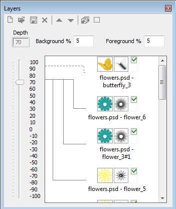
Fig. 4.26. Layers list
Layers are displayed being overlapped in the main window of the program. A green check mark on the right side of the toolbar shows if the set of layers is shown on the working area, while a check mark to the right of the layer shows if it is to take part in frame sequence generation.
We start by adjusting our project a little. To make one of the layers the background for a photo while all the rest are on top of it, we need to move the background image to the bottom of the list, putting the photo above it.
Click the left mouse button on the layer thumbnail image in the list or click on the image itself in the working area holding the Ctrl key to activate it (it will be highlighted with red). Then press the «down» button on the toolbar of the layers window to move the layer down. Buttons for moving up layers and deleting them are located nearby. After moving the photo down you'll get the necessary arrangement of the layers.
Attention!
Starting from 3DMasterKit version 4.0, the order of layers on the list corresponds to their actual location: the higher the layers is, the closer it is to the spectator. To change the position of the layer, select it by clicking and move the slider on the depth scale to set the desired value.
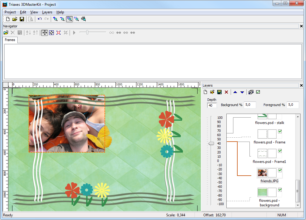
Fig. 4.27. A photo is smaller than a template
If the photo is a little bit smaller or bigger than a template, it is necessary to adjust the photo's size in that way, that it could be proportionally located on a template. For that select the Edit >> Transform >> Scale menu command (hot keys Alt+S ). After that, around the current image a running frame (marching ants) will appear. Press the left mouse button at any place on the screen, and, while holding it, adjust new proportions of the image being scaled. Release the left mouse button only when this is completed. Scaling is done in relation to the center of the image. In case of a wrong scale, repeat this step over.
Move the layer with the photo closer to the center of the template. Switch to the movement mode by clicking the right mouse button at any place on the screen. Click on the photo with left mouse button and drag it to the desired place, release the button when done.
You can change the location of any layer in the same way. It is sufficient to select it on the list and move to the desired position.
The Edit >> Transform >> Rotate menu command (hot keys Alt+R) allows rotation at user-specified angle. To exit the scaling and rotation mode press Esc or click the right mouse button.
Repetitive use of scale and rotation operations in 3DMasterKit does not cause the loss of image quality. At any stage of editing it is possible to undo or redo the recent actions.
To save the result choose Project >> Save project from the menu, or press Ctrl+S and type in the file name.
After completing our project composition, we set parallaxes values for the foreground and background in the respective fields – Foreground parallax and Background parallax. Then we allocate layers in depth in relation to each other. In order to do this we select a layer from the list and move up or down the depth scale slider.
Attention!
The optimal values of foreground and background parallaxes are defined by experiment. In this project as an example we set the value to 5, while you may try other values. In our opinion, the best result is achieved with the parallax values of 5 to 7.
After we have correctly allocated the layers on the canvas and set a relative depth, it is possible to set a map of depth for each of the layers (see also section 2.7). In order to do that we right click on the thumb-nail image of the layer which we want to attach a map of depth to and select Load depth map.
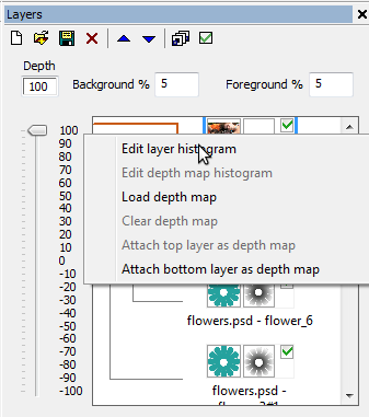
Fig. 4.28 Adding a depth map
A depth map can also be added when preparing a template in Photoshop. In this case a depth map will be stored as a separate layer directly in the template. When preparing for encoding in 3DMasterKit it will be necessary to specify which layer this depth map relates to. In order to do this a depth map layer has to be located below the original layer on the list. After that right click on the original layer thumb-nail image and select Attach layer below as depth map.
When adding a depth map a thumb-nail of it has to appear to the right of the icon.
The preparation stage is completed. Now we may proceed to the frame sequence generation process. Select the Layers >> Generate multilayer stereo menu command (hot keys: Alt+G). The Generate multilayer stereo dialog will appear (fig. 4.29).
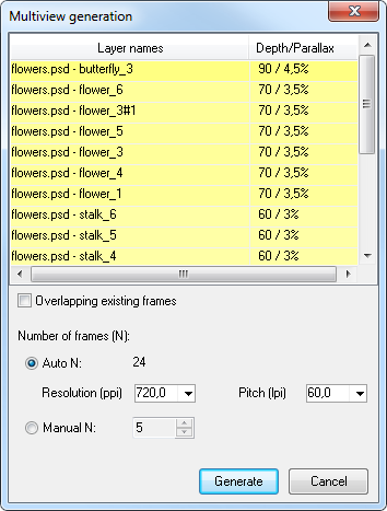
Fig. 4.29. Multiview generation dialog
In the Generate multilayer stereo dialog, depending on the relative depth set for the layer, the line on the list will be highlighted the with tint of blue or yellow color. Yellow means, that the layer will be “protruded” from the plane, blue color means that the layer will be in the depth. The further the layer is from the plane, the thicker is the tint of the line on the list.
In the Generate multilayer stereo window we choose automatic calculation of frame number (N), we also set the printer resolution (ppi) and lens pitch (lpi), then we click Generate. We can specify the frame number manually (Manual N). In this case we should know the minimal number of frames for stereo image creation.
To create an anaglyph photo 2 frames are enough, but if you want to get a lenticular multi-view stereo-image, a sequence of frames is required. A lenticular image is an integrated image, the overall 3D effect depends on the way all lenses work. The experience of using lenticular photos gives the refining coefficient for the formula of minimal frame number calculation (Nmin = Res / Pitch). The formula using this coefficient looks like this:
N = k * Res / Pitch,
where “N” is the frame number that is ample to get a good 3D effect, “k” – refining coefficient which equals 2, “Res” – printer resolution (in ppi) which is displayed in the status line of 3DMasterKit Print preview, Pitch – number of lenses per inch (lpi).
After adjusting all settings and pressing Generate we acquire a series of frames in the image list of the Navigator tab (image series in the top of the 3DMasterKit window) as shown in fig. 4.29. The Active and the Left frames are displayed with semi-transparent overlapping in the working area of the program. The rightmost image of the generated series of frames is set as the Active and the leftmost set as the Left frame by default.
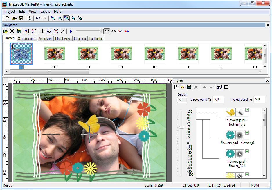
Fig. 4.30. Generated frames sequence
After generating frames, layers are no longer shown in the workin area - we notice that the check mark in the toolbar has disappeared. Thus, layers do not cover the finished images. The layer view switches on automatically when actions with layers are performed.
This provides the way to conveniently process several photos in one template using following scheme:
a) several photos are added to the template;
b) all photos are located at the zero layer;
c) viewing flags are used (check marks at thumb-nail images on the list of layers) and the needed photo is chosen;
d) a frame sequence and a lenticular image are generated.
Steps "c", "d" are repeated for each photo added to the template.
If for whatever reason you are not satisfied with the generated frames series (e.g. there was a mistake in parameters), it is possible to undo the generation by pressing Ctrl+Z, choosing Edit >> Undo menu command, or selecting the respective frames and pressing the Delete key.
Working with lists in 3DMasterKit is similar to working with Windows lists: you can select a group of objects holding the Shift key, or separate objects by pressing Ctrl. To make all layers invisible it is necessary to select the extreme layer, press Shift and click the check mark to the right of the layer located on the other side of the list.
To quickly evaluate the stereo effect you may switch to the anaglyph mode and use colored glasses (fig. 4.31).
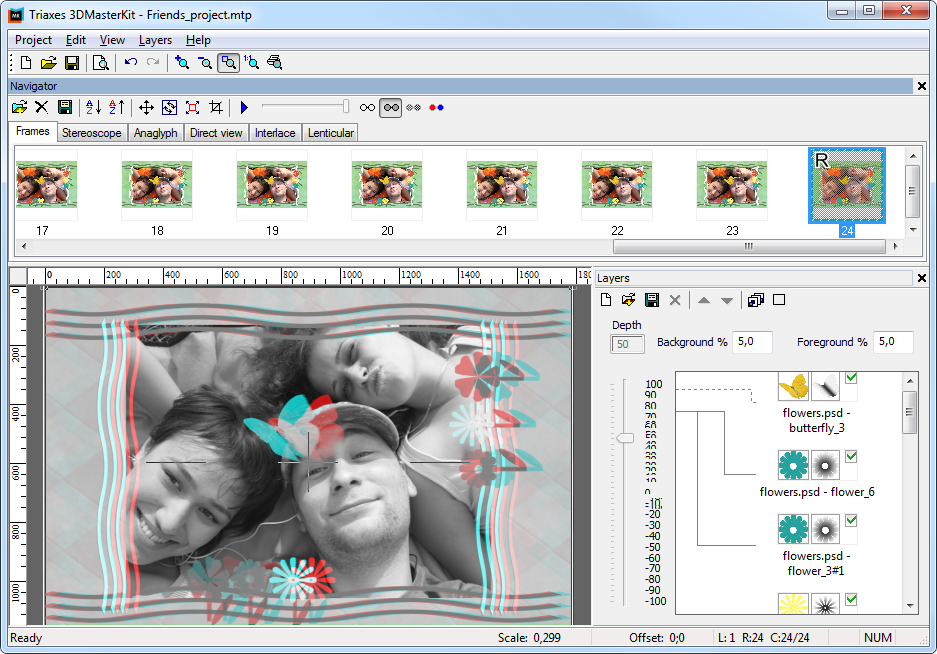
Fig. 4.31. Anaglyph view mode for frame series
If you have no anaglyph glasses at hand, a stereo effect can be seen by creating a stereo pair for direct view (Direct view tab). The stereo pair is shown in fig. 4.32. In order to see dimensions look at the photo, relax your eyes as you do when you look into the distance. If you have managed to do that, you are going to see three pictures, and the one in the center will be in 3D.
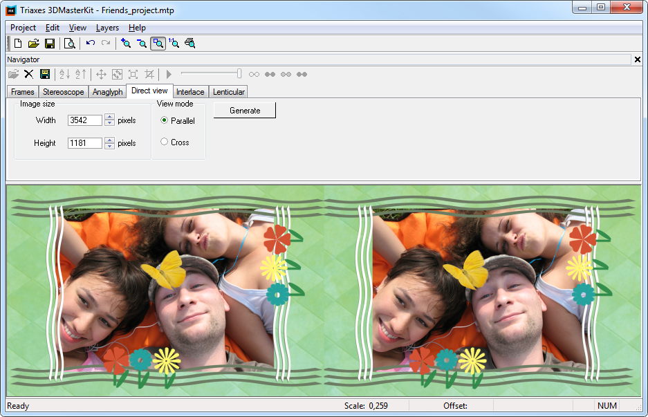
Fig. 4.32. Stereo pair for a direct view (parallel method)
You can save the generated sequence of frames on disc, with the Project >> Export frames menu command.
The generated frames are modeling a multi-view stereo photograph. The frames are already aligned in relation to each other, so there's no need to make a compensating shift, you may switch directly to the tab with the needed encoding method.
E.g., in fig. 4.33 anaglyph stereo photography creation is shown.
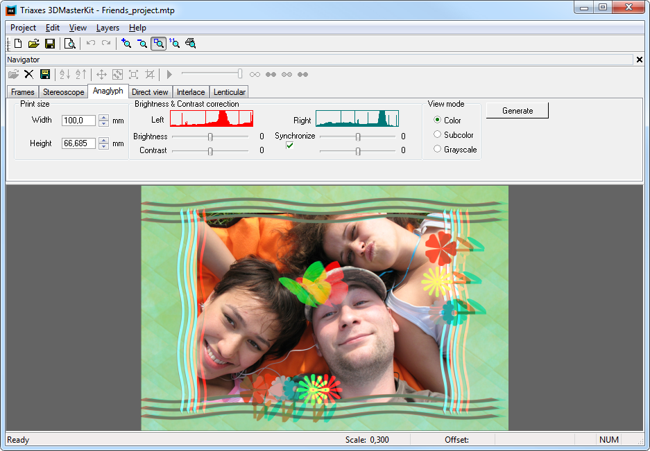
Fig. 4.33. Anaglyph stereo picture
For the lenticular encoding, turn to the Lenticular tab, and adjust the size and the pitch of the lenticular screen, select the resolution and click Generate. The result is shown in fig. 4.34; after that print the image and attach it to the lenticular screen.
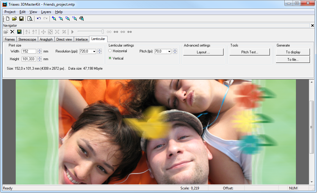
Fig. 4.34. An encoded image for lenticular stereo image