4.3 Principles of direct printing on the lens
Most plotters for direct printing have special printing software for printing process control. Triaxes Legend is intended to generate encoded images for viewing via lenticular lens. If you are not going to mirror the image with special printing software, do not forget to mark it with the Mirroring tick before encoding. To create a file with the encoded image use encoding To file... (fig. 4.3.1).
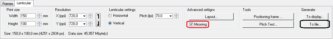
Fig. 4.3.1. Encoding to file option
Before printing it is necessary to properly position the lens on the printing table in order to match the lens and the encoded bands.
To do so generate the positioning frame and print it on the printing table (fig. 4.3.2).
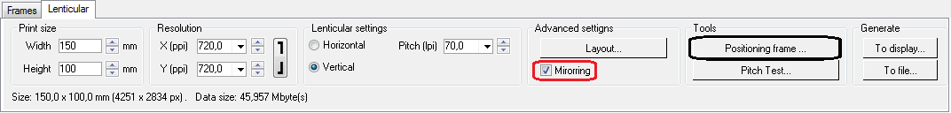
Fig. 4.3.2. Calling up Positioning frame dialog
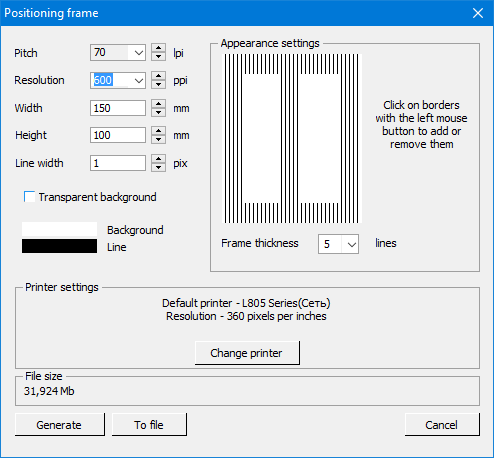
Fig. 4.3.3. Positioning frame dialog
Adjust the appearance of the frame in the Appearance settings block. It is possible to add/remove the borders (up and down, on each side and on the center). Use the left mouse button.
It is necessary to specify the precise lens pitch, therefore make a pitch test beforehand.The easiest way is to print a pitch test on paper or more preferably on white glossy film providing less ink spreading, which gives a more precise result, since the film is closer to the lenticular material in terms of its surface features unlike paper.
Then one should put a lens on the printed pitch test and find the proper value. The pitch test is made with the estimated viewing distance taken into account, i.e. when the final 3D image is supposed to be viewed from the 1-meter distance then you make the pitch test so that you look at it from the same 1-meter distance. Read more about the pitch test in Pitch test.
Now using the lens pitch (optical resolution) one can encode and print the positioning frame. It is recommended to set the 1-px line width. Select the color of frame borders (black or white) for printing on white and black printing tables correspondingly. It is possible to select the background color (white is set by default) and also the transparent background.
The pitch of the positioning frame should equal the pitch of the lens that has been found. The width of the positioning frame should equal the size of the future lenticular image. It is important for the positioning frame to have the central line as well as the left and the right boundary lines.
It is possible to generate the frame To display and To file.... Generate it to a file if your plotter has special printing software.
It is important to match the frame and the origin of coordinates of the encoded image.
Figure 4.38 shows the example of positioning frame printing using Mimaki A3.
Note! When encoding a positioning frame it is necessary to use the horizontal resolution of the plotter printing profile (or multiple values).
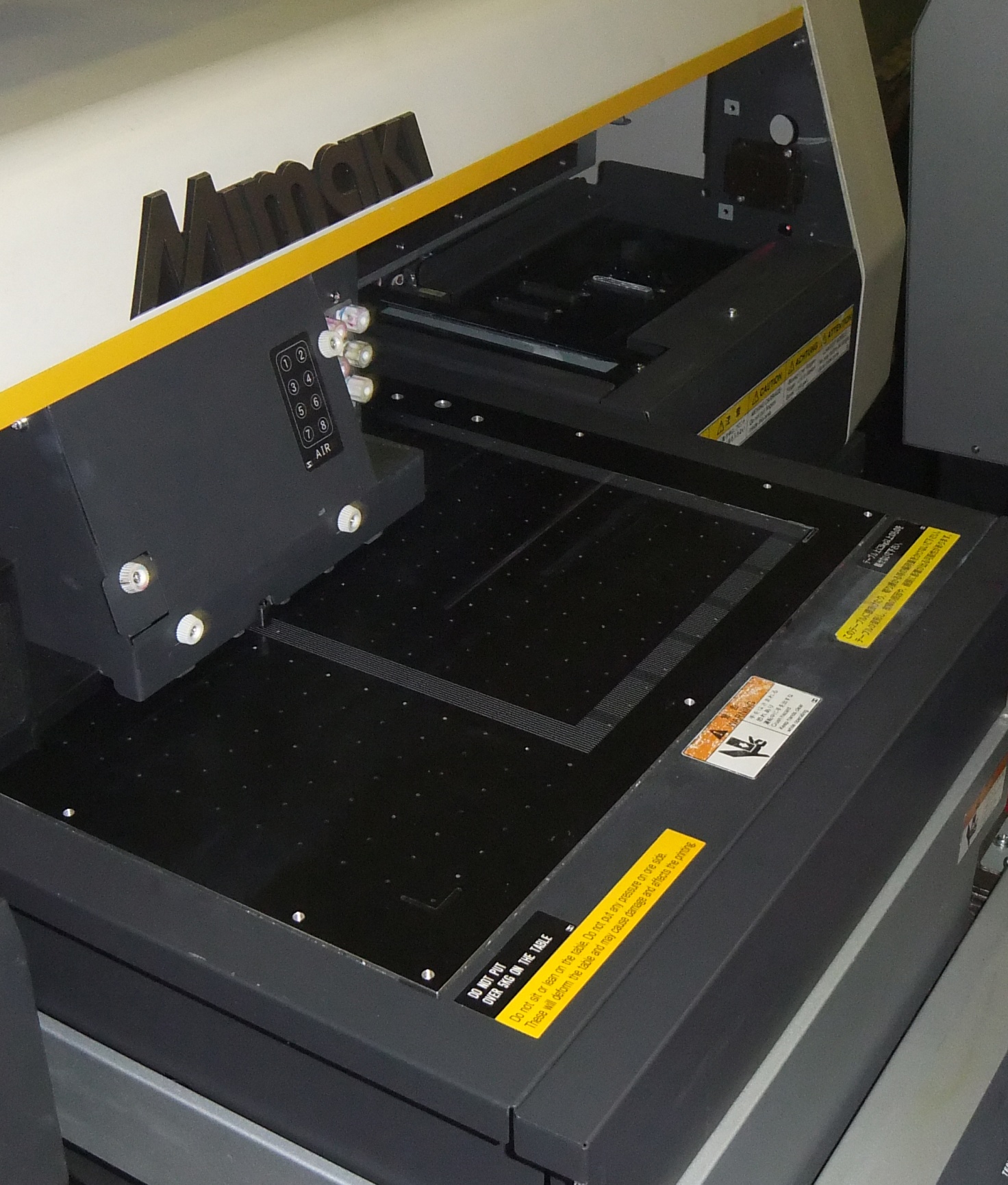
Fig. 4.3.4. Positioning frame printing on Mimaki A3 printing table
Then it is necessary to position the lenticular lens in such a manner that you can see all lines without zigzags. To get more precise positioning you can use additional devices such as the lantern, magnifier or digital microscope enabling to see the lines more clearly (Fig. 4.38).
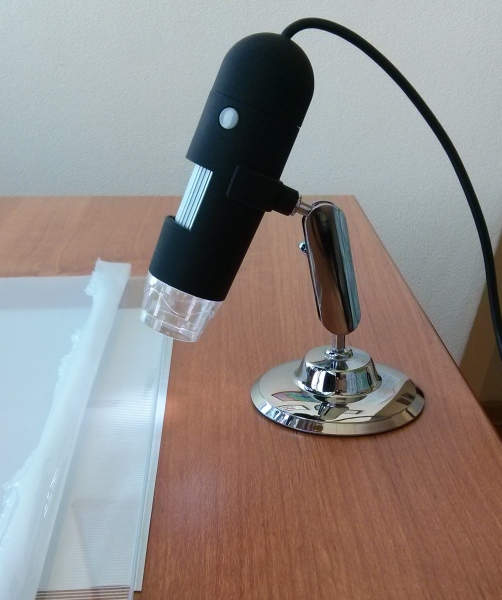
Fig.4.3.5. Digital microscope
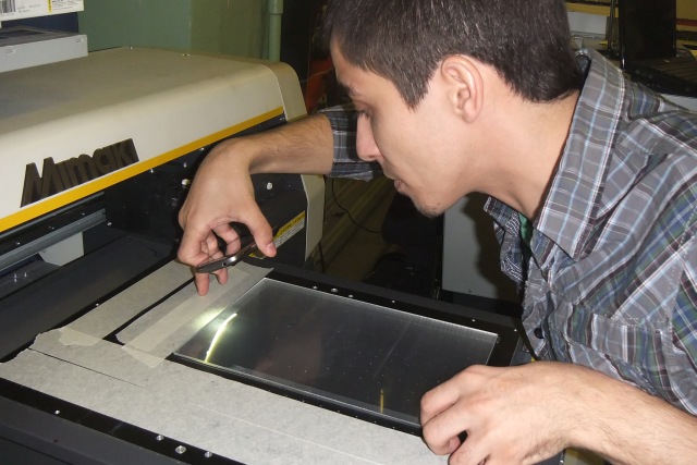
Fig.4.3.6. Lenticular lens positioning on a plotter's printing table
When the frame lines are between sheet lenses, one almost cannot see them — this is the right position (Fig. 4.39).
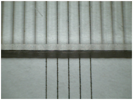
Fig. 4.3.7. Correct position of frame lines
Note! The positioning goes using the central line of the positioning frame. It is necessary to position the lens in the way that the frame lines are between sheet lenses, equally along the whole length of the sheet — it ensures the frame lines are parallel to sheet lenses and results in precise matching. It is necessary to fix the lens on the table after positioning. The vacuum hold-down is a perfect tool.
Now one can start printing. It is necessary to send the file saved by Triaxes Legend to the UV plotter printing software. You need to switch on a vacuum pump to fix the lens for printing.
Note! To match the encoded image with the lens it is necessary to print the encoded image from the same starting printing point as in the case with the positioning frame.
Proper matching of the encoded image with the lens means the image code stripes are placed accurately under the lenticular sheet lenses. It allows you to perceive the lenticular effects, such as: 3D, flip, animation, morphing, zoom, – without artifacts (doubling, show-through, shallow depth, bad switching). This is one of the keys to success.
After printing it is necessary to close the back side of the image with the white film layer to avoid the show-through effect.
Our experts tested direct image printing prepared in Triaxes Legend on Arizona OCE 360, Mimaki UJF-3042, Mimaki JFX-1615, Roland LEF-20 and SUN plotters. We made tests using 20 – 70 lpi lenses of different sizes: from A4 up to 120×60 cm.
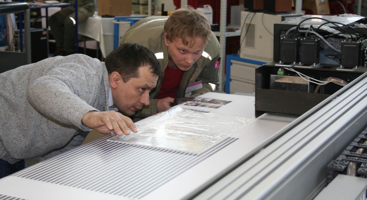
Fig. 4.3.8. Working with one of UV plotters
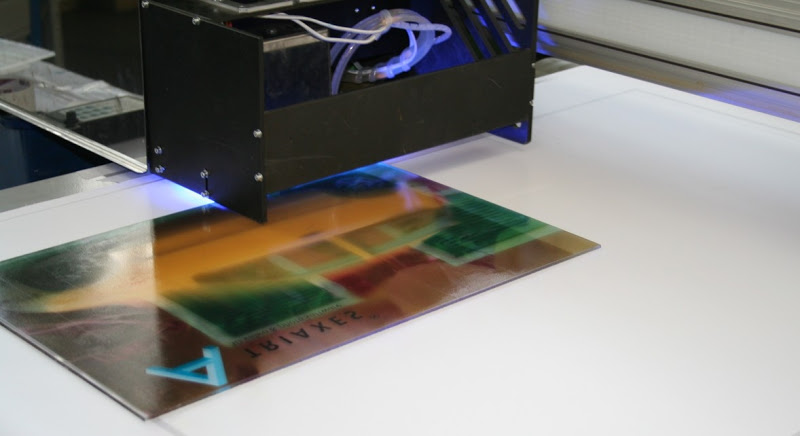
Fig. 4.3.9. Lenticular example with morphing effect