2.7 Program settings
3D Event Live VUE settings appear as a dialog window with tabs (Fig. 2.12):
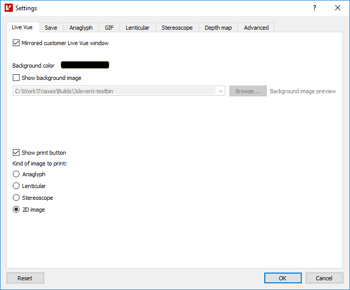
Fig. 2.12. Live VUE tab
The Live VUE tab contains the settings for the software general appearance and parameters of the Live VUE mode:
Mirrored customer Live VUE window - show/hide the mirrored video captured from the camera in the Live VUE window;
Background color - allows you to set the background color in the Live VUE window;
Show background image - choose the image from your computer that will be used as a background image in the Live VUE window;
Show print button - show the Print button in the Live VUE window;
Kind of image to print - image type that will be sent to the printer when you click the corresponding button in the Live VUE window.
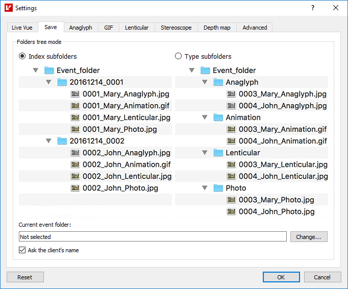
Fig. 2.13. Save tab
In Fig. 2.13. you can see two options for project output images saving.
Saving Option 1 Every time you save during the session a new folder (date + sequence number) with all project images is created in the specified folder. Files in the folder are named in the following way: № + project name + image type;
Saving Option 2 Every time you save during the session new folders are created according to the image type (Anaglyph, Animation, Lenticular, Photo). Files are named in the same way as in Option 1, but they are located in folders according to their type.
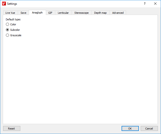
Fig. 2.14. Anaglyph tab
In Fig. 2.14. you can see anaglyph image settings.
Default type - types of the generated anaglyph: color, subcolor and grayscale.
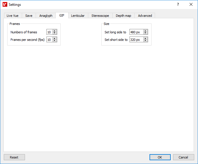
Fig. 2.15. GIF (Animation) tab
In Fig. 2.15. you can see animation properties and size.
Numbers of frames - frame number changes within the range of 2 to 32;
Frames per second (fps) - speed changes from 1 to 60 frames per second;
Set long/shot side to - width/height in pixels changes within the range of 32 to 3840.
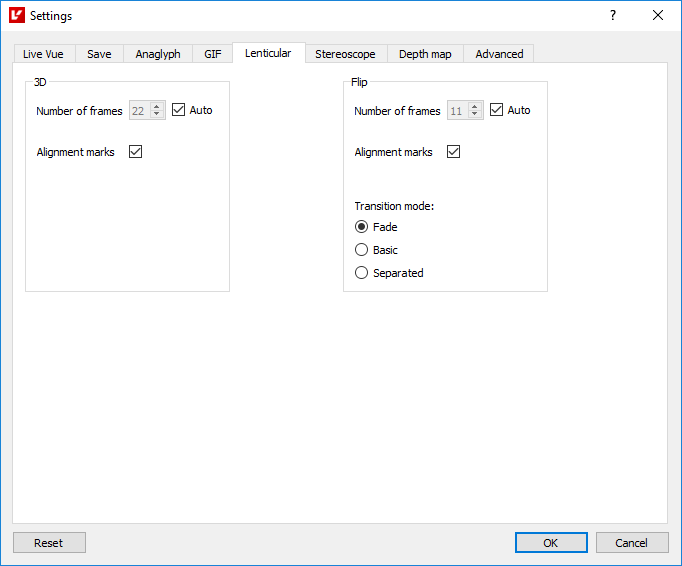
Fig. 2.16. Lenticular tab
In Fig. 2.16. you can see lenticular generation settings:
Numbers of frames - frame number is set by the user (from 2 to 32) or automatically (auto). It is calculated differently for 3D and Flip project types;
Alignment marks - show/hide the frame with additional markers that allow matching the lenticular with the image.
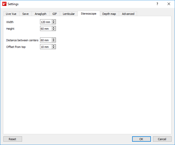
Fig. 2.17. Stereoscope tab
In Fig. 2.17. you can see the properties and size of the stereoscope image:
Height/Width - height/width of the stereoscope card is measured within the range of 1 to 200;
Distance between centers - distance in mm between centers of stereoscope card images changes within the range of 1 to 100;
Offset from top - distance in mm from the image edge to the stereoscope card edge is measured within the range of 0 to 100.
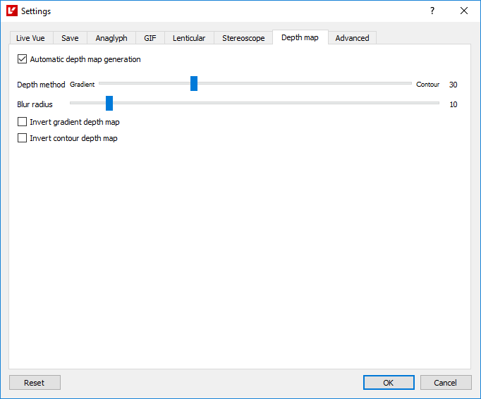
Fig. 2.18. Depth map tab
In Fig. 2.18. you can see depth map generation settings:
Automatic depth map generation - the function can be applied for the 3D project wizard, when a photo is added, when a new layer is created, or when the camera takes shots in the Live VUE mode.
Depth method allows you to combine 2 depth map creation methods and set the degree for each of them. A value of "0" corresponds to the depth map generated entirely with the gradient method, while the value of "100" corresponds to the contour method;
Blur radius - degree of blur for the mixed-mode depth map. Value range: 0..100;
Inversion of the depth map for each of the 2 methods.
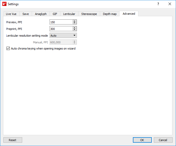
Fig. 2.19. Advanced tab
In Fig. 2.19. you can see advanced program settings:
Preview, PPI - image resolution on the screen;
Preprint, PPI - image resolution on the print preview page;
Lenticular resolution - you can choose the Lenticular resolution mode that will be used for lenticular image generation: auto or manual. You can input the value in the entry field below;
Auto chroma keying (3D/Flip wizard) - the function can be applied for the 3D/Flip wizard, when a photo is added, or when a new layer is created.