3.4 Marking and correcting images
Marking images
The marking means setting two images from a series as the Left and the Right frames. The Left and the Right frames set the boarders of the frame sequence, which participates in stereo image generation. In order to set an image as the Left frame, it is necessary to right-click on the necessary image and then select Set left on the list of the context menu that will appear. The same goes with setting a frame as the Right one.
When you create anaglyph stereo images, cards for the stereoscope, cards for parallel or cross-eyed viewing methods, only frames set as the Left and the Right ones will participate in generation.
When you create lenticular images, all frames between the Left and the Right one will participate in generation. The remaining frames which are more to the left from the Left one and more to the right from the Right one, will be marked by the black-and-white color and won't participate in generation.
There is also a concept of the Active image.
The Active image in 3DMasterKit is an image selected at the moment. In order to select an image, i.e. make it Active, it is necessary just to left-click on its thumbnail.
The image set as the Active one is marked by a blue frame and is always shown superimposed over the Left frame with the transparency specified by the slider in the software working area.
It is necessary for vertical and horizontal alignment of a frame series and also for zero parallax plane setting.
Image moving
The right image of a stereo pair is always displayed above the left one. To specify a zero parallax object, correct the position of the right image relative to the left one.
Menu command: Edit >> Transform >> Move
Hot keys: Alt+M
Toolbar button: 
In the moving mode, the mouse pointer has additional arrows indicating moving 
Any image can be moved relative to the canvas. The image motion operation is applied to the Active image, towards the current (selected) object. To mark an image you should click on it in the list of the thumb-nail images.
To move an image, hover the mouse pointer on the object you focus on. Then click the left or right mouse button, which will correspond to the one of two moving modes. After that hold down the mouse key and move the mouse pointer to the desired position.
The process of moving the image will be finished at the point where the mouse button is be released.
The modes of moving differ in the following way: if you hold down the right mouse button, a line is drawn from the initial point to the current position of the pointer, but if you hold down the left mouse button, the image moves together with the pointer.
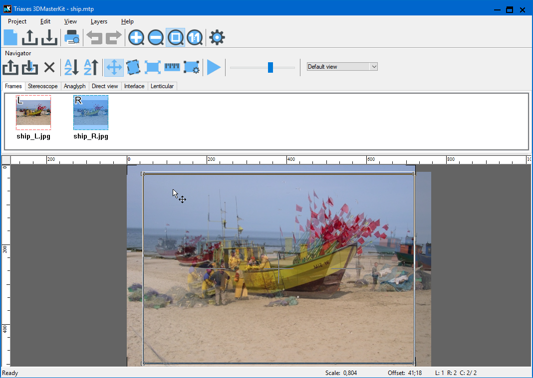
Fig. 3.4.1. Image moving
Useful tip: If you click one of the mouse buttons during the operation with the other mouse button being held down, the operation is canceled. This rule is also applied to other operations: scaling and rotating.
If you create a lenticular stereo image out of a sequence of frames taken with a parallel method, the setting of the zero parallax object must be done for all images in the sequence.
Besides, it is very convenient to align images using keyboard buttons without the mouse and switching between frames with Ctrl + left/right arrow buttons.
Automove
Menu command: Edit >> Automove
The automove operation is used when preparation of a stereo sequence for lenticular encoding takes place.
In order to use the Automove command, it is necessary to set the leftmost image as the Left frame and the rightmost – as the Right one. After that, perform vertical alignment and combine them by a zero parallax object. Then select the Edit >> Automove menu command.
As the result, all the in-between frames will be automatically combined by the principle of proportionality. After that, it is necessary to select all the rest frames in turn (make them Active) and perform the final zero parallax point correction. Then proceed to encoding.
Rotating images
Sometimes in the course of stereo photography, especially manual, you can fail to keep the cameras parallel to the horizon. This defect also reduces the stereo effect. You can compensate this defect by rotating images.
Menu command: Edit >> Transform >> Rotate
Hot keys: Alt+R
Toolbar button: 
The rotation operation is applied to the Active image. To set an image as the Active one, left-click on it.
In the rotation mode, the mouse pointer has additional arrows indicating rotation![]() .
.
To rotate an image, press the left mouse button, move the mouse pointer to the new position and release the button. The image will be rotated and the initial point will be moved to the final rotation point.
The image is rotated around the center of the crop frame. The initial and final rotation points are joined by an arc. The rotation angle is displayed next to the rotation center as two numbers: the angle before the operation + the current rotation angle.
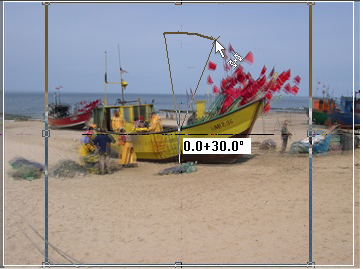
Fig. 3.4.2. Initial image rotation
In the rotation mode you can change the size and the position of the crop frame and thus set the rotation center to the position you need.
If you right-click during rotation (when the left mouse button is pressed), the current operation will be canceled.
To exit the rotation mode, just right-click or press Esc.
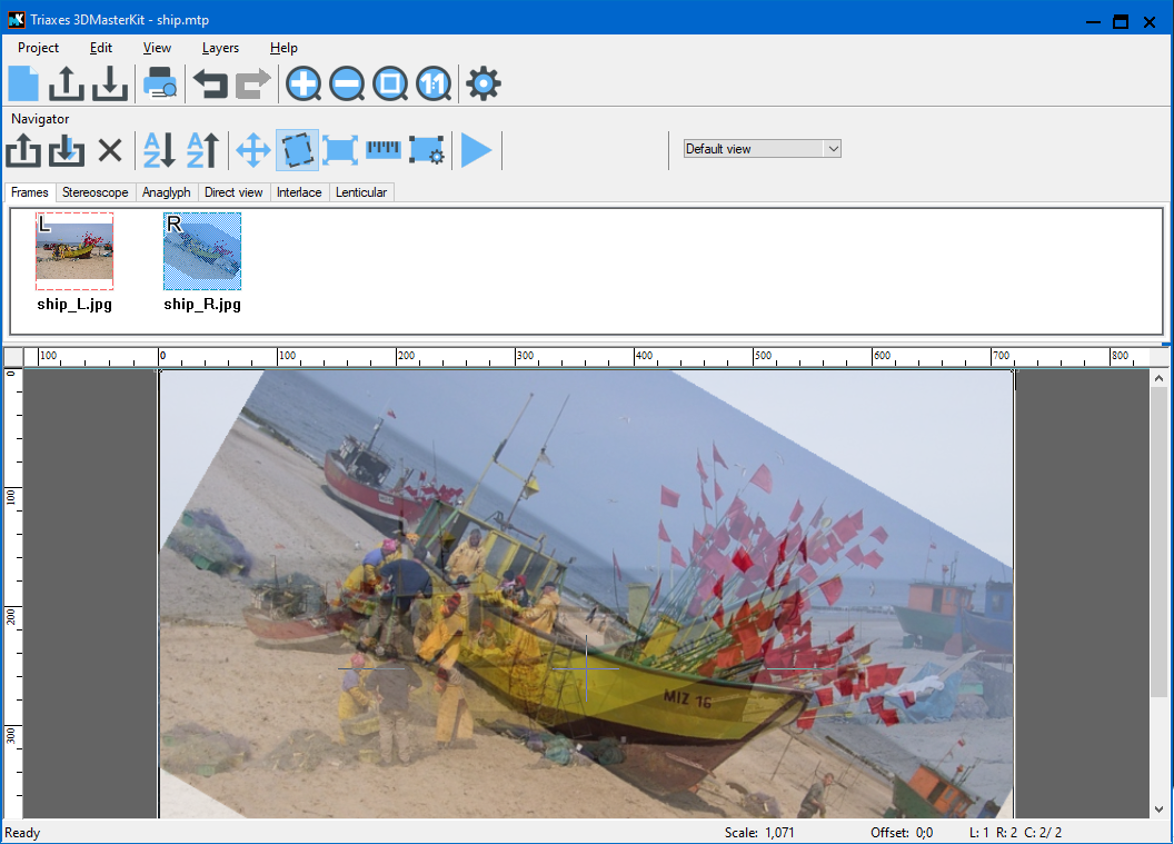
Fig. 3.4.3. Rotation result
Here is a practical example of image correction. In the picture you can see that there was a slight defect when the stereo pair was taken: horizon lines are not parallel.
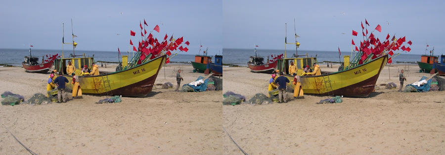
Fig. 3.4.4. The example of the image correction (initial state)
Correct the right frame first. Set the Opacity slider to the rightmost position. Change the size of the crop frame so that the crosshair is on the horizon line of the image. Enable the rotation mode for the right frame. Point the mouse pointer to the horizon line and move it so that it matches the horizontal line of the crosshair.
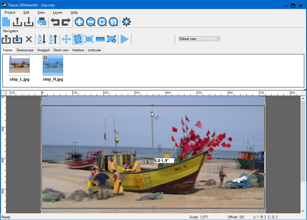
Fig. 3.4.5. Adjusting the horizon line
Do the same for the left frame. Then you should only specify the zero parallax object and crop the image.
Rotate precise mode
The Edit >> Transform >> Rotate Precise menu command is used for the exact angle rotation of an image.
Hot keys: Ctrl+Alt+R
The command opens a dialog allowing you to specify the exact rotation angle (Fig. 3.4.6).
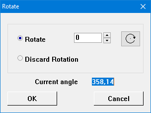
Fig. 3.4.6. Rotate precise dialog
You must specify the rotation angle in the Rotate field. You can specify the angle either manually or using the "scrolling” buttons with arrows. You can specify the direction of rotation using the  button located near the field. A click on this button changes the direction of rotation to the opposite one.
You can undo all the previous rotations by marking the Discard Rotation option. Click ОК to apply rotation or Cancel to close the dialog without applying the changes.
Scaling images
Menu command: Edit >> Transform >> Scale
Hot keys: Alt+S
Toolbar button: 
The scaling operation allows you to correct inaccuracies in the scale of the source frames caused by the camera automatic focus. If the scale of objects represented on a series of frames differs, you can take the scale of the left frame as a basis to adjust the sizes of objects on all frames.
Useful tip: Scaling can also be used to create a lenticular image with the zoom effect. To do it, add a sequence consisting of copies of the same image to the list of frames, set a gradually increasing scale for this sequence and align frames by the selected object.
In the scaling mode, the mouse pointer changes its form: squares of different sizes that appear next to the arrow  , and black marching ants that appear around the currently selected image. To scale the image, press the left mouse button on the screen, move the mouse pointer to the new position and release the button. Scaling is always done relative to the initial size of the image. The scaling percentage is shown near the center of the window.
Scale precise dialog
The Edit >> Transform >> Scale Precise command in the menu is used to scale images precisely.
Hot keys: Ctrl+Alt+S
The command opens a dialog allowing you to specify the necessary scale (Fig. 3.4.7).
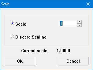
Fig. 3.4.7. Scaling dialog
The scale value is entered in the Scale field.
You can undo all scale changes by marking the Discard Scaling option.
Click ОК to apply the new scale to the current image or Cancel to close the dialog without applying the changes.
Correcting a Histogram
Menu command: Edit >> Transform >> Histogram
Hot keys: Ctrl+Alt+H
The command opens a dialog allowing you to edit histogram settings for every image (Fig. 3.4.8).
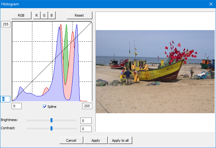
Fig. 3.4.8. Histogram correction dialog
Histogram (in photography) — is a graph of semi-tones allocation that has two axes: the x axis represents the brightness, and the y axis represents the relative number of pixels with corresponding brightness values.
By the histogram you can find out the main idea of exposition correctness, image contrast and color depth, and also define the required correction when you take a photo (changing exposition and color balance, light or image composition) and also when processing is started.
Use the buttons above the histogram to correct it by separate color channels: RGB – all channels, R – red channel, G – green channel, B – blue channel. By clicking Reset you can go back to the source histogram.
Set the control point by left-clicking. Remove the control point by right-clicking. Move the control point by left-clicking on the graph and holding the point while you're moving it to the necessary place.
There are two ways to connect controlling points: the spline and the broken line. Use the Spline flag under the histogram to enable/disable the spline mode. Fields by the x and the y axes allow to correct the brightness of borders manually. Besides, they can be moved by left-clicking on the required border.
Below the histogram there are Brightness and Contrast sliders to set image brightness and contrast.
With the help of the histogram one can noticeably increase the image quality. The below histogram does not have optimal distribution. For optimal correction move the right border nearer to the histogram:
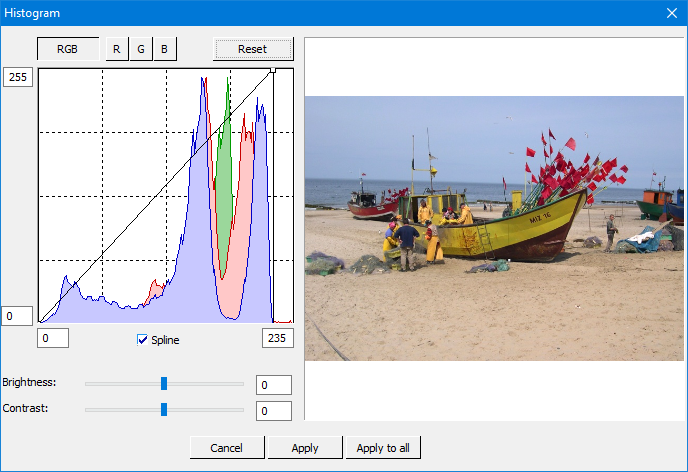
Fig. 3.4.9. Histogram correction dialog (continuation)
The above image contains too much of red color. It is easy to correct it. Toggle into the red channel (R), put a point on the histogram and move it a little.
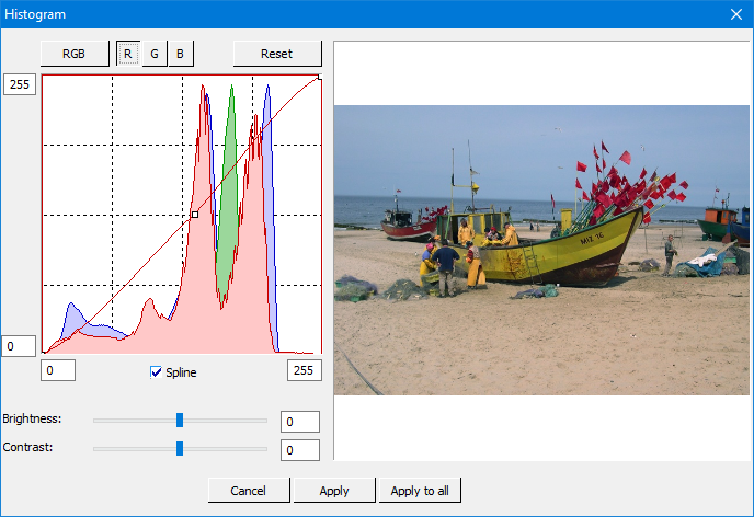
Fig. 3.4.10. Histogram correction dialog (completion)
By clicking Apply to all, the histogram correction is applied to all frames.